Theft Deterrent System Security Horn Circuit
DESCRIPTION
WIRING DIAGRAM
INSPECTION PROCEDURE
PERFORM ACTIVE TEST USING INTELLIGENT TESTER (SECURITY HORN)
INSPECT SECURITY HORN ASSEMBLY
CHECK WIRE HARNESS (MULTIPLEX NETWORK BODY ECU - SECURITY HORN ASSEMBLY)
THEFT DETERRENT SYSTEM - Security Horn Circuit |
DESCRIPTION
- When the theft deterrent system is operating, the multiplex network body ECU outputs a signal continuously at 0.4 second intervals, causing the security horn to sound.
WIRING DIAGRAM
INSPECTION PROCEDURE
| 1.PERFORM ACTIVE TEST USING INTELLIGENT TESTER (SECURITY HORN) |
Select the Active Test, use the intelligent tester to generate a control command, and then check that the security horn sounds.
Multiplex network body ECUItem
| Test Details
| Diagnostic Note
|
Security Horn
| Security horn ON/OFF
| -
|
- OK:
- Security horn operates normally.
| OK |
|
|
|
| REPLACE COWL SIDE JUNCTION BLOCK RH (MULTIPLEX NETWORK BODY ECU) |
|
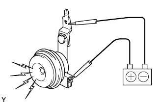
| 2.INSPECT SECURITY HORN ASSEMBLY |
Remove the security horn.
Check operation of the horn.
- OK:
Measurement Condition
| Specified Condition
|
Battery positive (+) → Terminal 1
Battery negative (-) → Horn bracket
| Horn sounds
|
| | REPLACE SECURITY HORN ASSEMBLY |
|
|
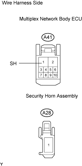
| 3.CHECK WIRE HARNESS (MULTIPLEX NETWORK BODY ECU - SECURITY HORN ASSEMBLY) |
Disconnect the A41 ECU connector.
Disconnect the A28 horn connector.
Check the resistance of the wire harness side connectors.
- Standard resistance:
Tester Connection
| Specified Condition
|
A41-1 (SH) - A28-1
| Below 1 Ω
|
A41-1 (SH) or A28-1 - Body sound
| 10 kΩ or higher
|
| | REPAIR OR REPLACE HARNESS AND CONNECTOR |
|
|
| OK |
|
|
|
| REPLACE COWL SIDE JUNCTION BLOCK RH (MULTIPLEX NETWORK BODY ECU) |
|