3Gr-Fe Compressor And Pulley -- Installation |
| 1. ADJUST COMPRESSOR OIL |
When replacing the compressor with a new one, after gradually discharging the refrigerant gas from the service valve, drain the following volume of oil from the new compressor before installation.
- Standard:
- (Oil capacity inside a new compressor: 130 + 15 cc (4.6 + 0.51 fl.oz.)) - (Remaining oil amount in the removed compressor) = (Oil amount to be removed from the new compressor when replacing.
- NOTICE:
- When checking the compressor oil level, observe the precautions in the cooler removal/installation.
- If a new compressor is installed without removing some oil remaining in the pipes of the vehicle, the oil amount becomes excessive. This prevents heat exchange in the refrigerant cycle and causes refrigerant failure.
- If the volume of oil remaining in the removed compressor and magnetic clutch is too small, check for oil leakage.
- Be sure to use ND-OIL 8 for compressor oil.
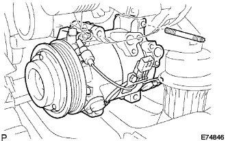
| 2. INSTALL COMPRESSOR ASSEMBLY |
Using an E8 "torx" socket, install the compressor with the stud bolt.
- Torque:
- 10 N*m{102 kgf*cm, 7 ft.*lbf}
 |
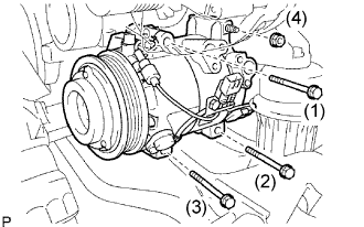
Install the compressor with the 3 bolts and nut.
- Torque:
- 24.5 N*m{250 kgf*cm, 18 ft.*lbf}
- NOTICE:
- Tighten the bolts in the order shown in the illustration to install the compressor.
 |
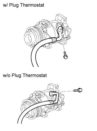
| 3. INSTALL DISCHARGE HOSE SUB-ASSEMBLY |
Remove the attached vinyl tape from the discharge hose.
 |
Apply sufficient compressor oil (ND-OIL 8) to a new O-ring and the fitting surface of the compressor.
- Compressor oil:
- ND-OIL 8 or equivalent
Install the O-ring on the discharge hose.
Install the discharge hose on the compressor with the bolt.
- Torque:
- 9.8 N*m{100 kgf*cm, 7 ft.*lbf}
| 4. INSTALL NO. 1 COOLER REFRIGERANT SUCTION HOSE |
Remove the attached vinyl tape from the suction hose.
 |
Apply sufficient compressor oil (ND-OIL 8) to a new O-ring and the fitting surface of the compressor.
- Compressor oil:
- ND-OIL 8 or equivalent
Install the O-ring on the suction hose.
Install the suction hose on the compressor with the bolt.
- Torque:
- 9.8 N*m{100 kgf*cm, 7 in.*lbf}
| 5. INSTALL ENGINE UNDER COVER |
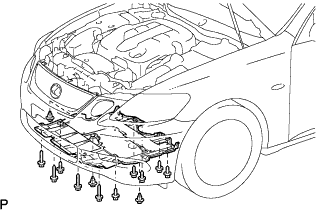 |
Install the under cover with the 3 clips and 10 screws.
| 6. INSTALL V-RIBBED BELT |
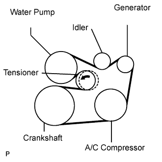
Install the V-ribbed belt.
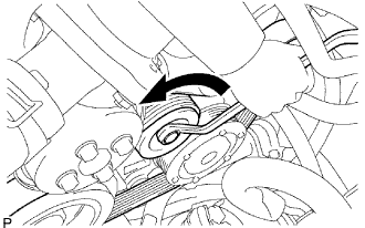 |
While turning the belt tensioner counterclockwise, remove the bar.
- NOTICE:
- Put the backside of the V-ribbed belt on the tensioner pulley and idler pulley.
- Check that the V-ribbed belt is properly set to each pulley.
If it is difficult to install the V-ribbed belt, perform the following procedure.
Put the V-ribbed belt on everything except the tensioner pulley as shown in the illustration.
While releasing the belt tension by turning the belt tensioner counterclockwise, put the V-ribbed belt on the tensioner pulley.
- NOTICE:
- Put the backside of the V-ribbed belt on the tensioner pulley and idler pulley.
- Check that the V-ribbed belt is properly set to each pulley.
 |
| 7. INSTALL V-BANK COVER SUB-ASSEMBLY |
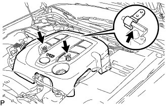 |
Install the V-bank cover with the 2 nuts.
- Torque:
- 5.0 N*m{51 kgf*cm, 44 in.*lbf}
| 8. INSTALL NO. 1 AIR CLEANER INLET |
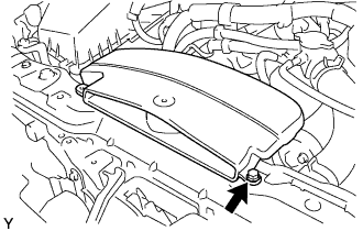 |
Install the air cleaner inlet with the bolt.
- Torque:
- 5.0 N*m{51 kgf*cm, 44 in.*lbf}
| 9. INSTALL ENGINE ROOM SIDE COVER LH |
Install the side cover with the 3 clips.
 |
| 10. CONNECT CABLE TO NEGATIVE BATTERY TERMINAL |
| 11. CHARGE REFRIGERANT |
Perform vacuum purging using a vacuum pump.
Charge refrigerant HFC-134a (R134a).
- Standard:
- 450 +- 50 g (15.87 +- 1.76 oz.)
- SST
- 07110-58060(07117-58060,07117-58070,07117-58080,07117-58090,07117-78050,07117-88060,07117-88070,07117-88080)

- NOTICE:
- Do not operate the cooler compressor before charging refrigerant as the cooler compressor will not work properly without any refrigerant, and will overheat.
- Approximately 100 g (3.53 oz.) of refrigerant may need to be charged after bubbles disappear. The refrigerant amount should be checked by measuring its quantity, and not with the sight glass.
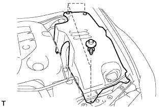
| 12. INSTALL COOL AIR INTAKE DUCT SEAL |
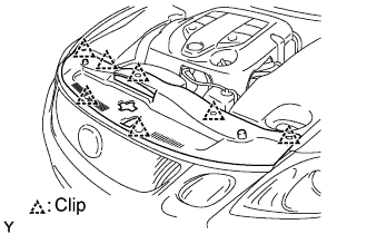 |
Install the intake duct seal with the 7 clips.
| 13. WARM UP ENGINE |
Warm up the engine at less than 1,850 rpm for 2 minutes or more after charging the refrigerant.
- NOTICE:
- Be sure to warm up the compressor when turning the A/C switch ON after removing and installing the cooler refrigerant lines (including the compressor), to prevent damage to the compressor.
| 14. CHECK FOR LEAKAGE OF REFRIGERANT |
After recharging the refrigerant gas, check for refrigerant gas leakage using a halogen leak detector.
Perform the operation under these conditions:
- Stop the engine.
- Secure good ventilation (the gas leak detector may react to volatile gases other than refrigerant, such as evaporated gasoline or exhaust gas).
- Repeat the test 2 or 3 times.
- Make sure that some refrigerant remains in the refrigeration system. When compressor is off: approximately 392 to 588 kPa (4 to 6 kgf/cm2 57 to 85 psi)
- Stop the engine.
Using a gas leak detector, check the refrigerant line for leakage.
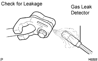 |
If a gas leak is not detected on the drain hose, remove the blower motor control (blower resistor) from the cooling unit. Insert the gas leak detector sensor into the unit and perform the test.
Disconnect the connector and leave the pressure switch on for approximately 20 minutes. Bring the gas leak detector close to the pressure switch and perform the test.
| 15. PERFORM INITIALIZATION |
Perform initialization (Click here).
- NOTICE:
- Certain systems need to be initialized after disconnecting and reconnecting the cable from the negative (-) battery terminal.