Blower Unit -- Removal |
| 1. REMOVE COOL AIR INTAKE DUCT SEAL |
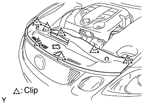 |
Remove the 7 clips and duct seal.
| 2. REMOVE ENGINE ROOM SIDE COVER LH |
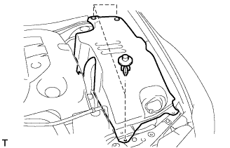 |
Using a clip remover, remove the 3 clips and side cover.
| 3. REMOVE FRONT PILLAR TO FRONT SIDE SEAL SUB-ASSEMBLY LH |
 |
Using a clip remover, detach the 3 clips and remove the side seal.
| 4. REMOVE FRONT PILLAR TO FRONT SIDE SEAL SUB-ASSEMBLY RH |
- HINT:
- Use the same procedures described for the LH side.
| 5. REMOVE FRONT WIPER ARM AND BLADE ASSEMBLY LH |
Remove the nut, wiper arm and blade.
| 6. REMOVE FRONT WIPER ARM AND BLADE ASSEMBLY RH |
Remove the nut, wiper arm and blade.
| 7. REMOVE FRONT FENDER TO COWL SIDE SEAL LH |
 |
Pull the cowl side seal in the direction indicated by the arrow in the illustration to detach the 2 claws and remove the cowl side seal.
| 8. REMOVE FRONT FENDER TO COWL SIDE SEAL RH |
- HINT:
- Use the same procedures described for the LH side.
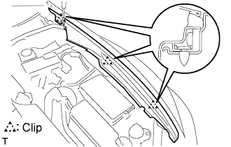
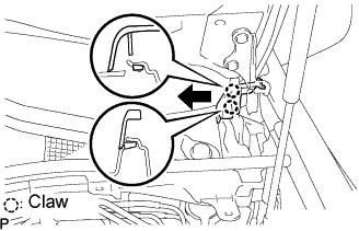
| 9. REMOVE COWL TOP VENTILATOR LOUVER SUB-ASSEMBLY |
Remove the 2 clips and detach the 5 claws.
 |
Pull the ventilator louver in the direction indicated by the arrow in the illustration to detach the 10 claws and remove the ventilator louver.
 |
| 10. REMOVE FRONT WIPER MOTOR AND LINK ASSEMBLY |
Disconnect the connector. Then detach the 2 clamps and remove the wire harness from the cowl top panel.
 |
Remove the 4 bolts and the wiper motor and link assembly.
- HINT:
- The 2 bolts labeled (A) in the illustration cannot be removed from the wiper motor and link because they are integrated into the wiper motor and link.
 |
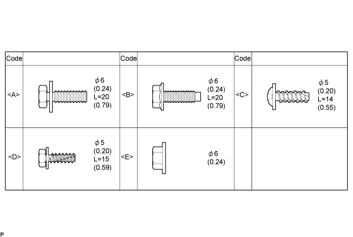
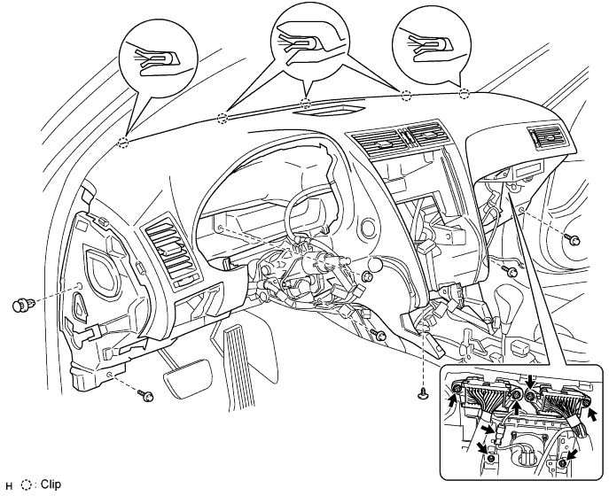
| 11. TABLE OF BOLT, SCREW AND NUT |
- HINT:
- All bolts, screws and nuts relevant to installing and removing the instrument panel are shown along with an alphabetical code in the table below.
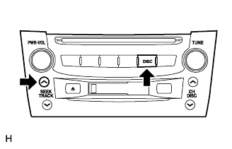
| 12. SET RADIO RECEIVER ASSEMBLY TO SHIPMENT MODE |
Remove all discs and tapes.
- NOTICE:
- If the discs or tapes cannot be removed, do not attempt to remove them forcibly. Send the unit to a repair shop.
Turn the engine switch off.
While simultaneously pressing the "SEEK UP" and "DISC" switches, turn the engine switch on (ACC).
- HINT:
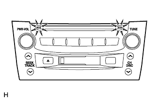
- The CD loading door indicator light blinks during mode setting and it remains lit after the setting is completed.
 |
Turn the engine switch off.
| 13. DISCONNECT CABLE FROM NEGATIVE BATTERY TERMINAL |
- CAUTION:
- Wait at least 90 seconds after disconnecting the cable from the negative (-) battery terminal to prevent airbag and seat belt pretensioner activation.
| 14. REMOVE FRONT DOOR SCUFF PLATE INSIDE RH |
- HINT:
- Use the same procedures described for the LH side.
| 15. REMOVE FRONT DOOR SCUFF PLATE INSIDE LH |
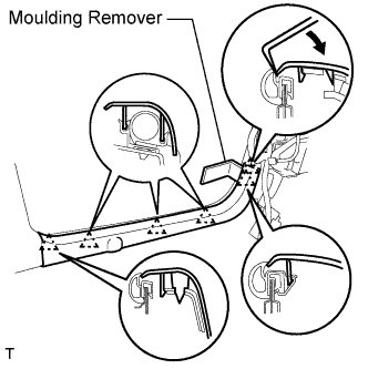 |
Using a moulding remover, detach the 5 claws and remove the scuff plate.
| 16. REMOVE FRONT DOOR OPENING TRIM COVER RH |
- HINT:
- Use the same procedures described for the LH side.
| 17. REMOVE FRONT DOOR OPENING TRIM COVER LH |
Using a moulding remover, detach the 3 claws and remove the trim cover.
| 18. REMOVE NO. 2 STEERING WHEEL COVER LOWER |
Using a screwdriver, remove the steering wheel No.2 cover lower.
- HINT:
- Tape up the screwdriver tip before use.
 |
| 19. REMOVE NO. 3 STEERING WHEEL COVER LOWER |
Using a screwdriver, remove the steering wheel No.3 cover lower.
- HINT:
- Tape up the screwdriver tip before use.
 |
| 20. REMOVE STEERING PAD |
Using a "torx" socket wrench (T30), loosen the 2 "torx" screws until the groove along the screw circumference catches on the screw case.
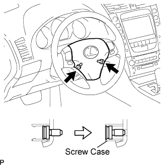 |
Pull out the steering pad from the steering wheel assembly and support the steering pad with one hand as shown in the illustration.
- NOTICE:
- When removing the steering pad, do not pull the airbag wire harness.
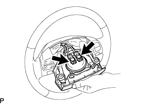 |
Disconnect the horn connector.
Disconnect the 2 connectors and remove the steering pad.
- NOTICE:
- When handling the airbag connector, take care not to damage the airbag wire harness.
| 21. REMOVE STEERING WHEEL ASSEMBLY |
For 3GR-FSE (Click here)
For 3UZ-FE (Click here)
| 22. REMOVE STEERING COLUMN COVER LOWER |
For 3GR-FSE (Click here)
For 3UZ-FE (Click here)
| 23. REMOVE STEERING COLUMN COVER UPPER |
For 3GR-FSE (Click here)
For 3UZ-FE (Click here)
| 24. REMOVE SPIRAL CABLE WITH STEERING SENSOR |
Disconnect the connectors from the spiral cable with steering sensor.
- NOTICE:
- When handling the airbag connector, take care not to damage the airbag wire harness.
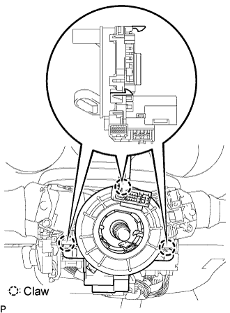 |
Disengage the 3 claws and remove the spiral cable with steering sensor.
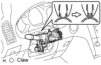
| 25. REMOVE WINDSHIELD WIPER SWITCH ASSEMBLY |
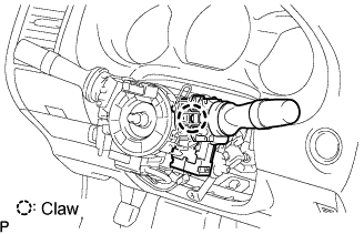 |
Disconnect the connector.
Detach the claw and remove the wiper switch.
- NOTICE:
- If the claw is pushed with excessive force, it may break.
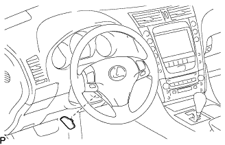
| 26. REMOVE HEADLIGHT DIMMER SWITCH ASSEMBLY |
 |
Disconnect the connector.
Detach the clamp from the dimmer switch as shown in the illustration.
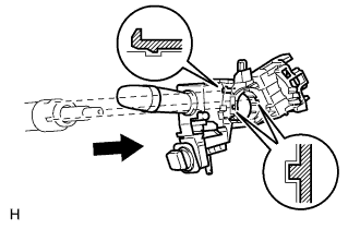 |
Detach the claw and remove the dimmer switch as shown in the illustration.
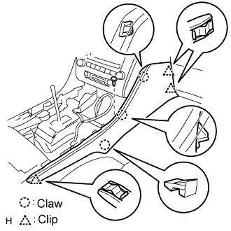
| 27. REMOVE FRONT CONSOLE UPPER PANEL ASSEMBLY |
 |
Using a clip remover, detach the claws and remove the garnish.
- HINT:
- Tape the clip remover tip before use.
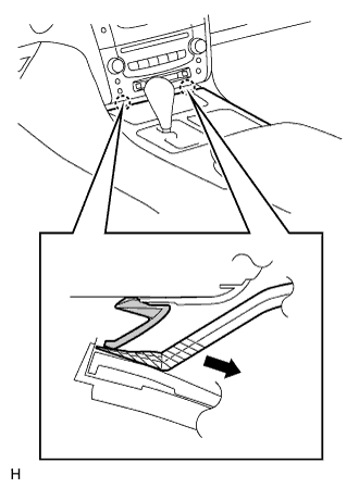
| 28. REMOVE CONSOLE UPPER PANEL ASSEMBLY |
 |
Twist the shift lever knob in the direction indicated by the arrow and remove it.
Using a screwdriver, detach the 9 clips.
- HINT:
- Tape the screwdriver tip before use.
 |
Remove the ash receptacle and then disconnect the connector.
| 29. REMOVE INSTRUMENT PANEL FINISH PANEL END RH |
 |
Remove the screw.
Using a screwdriver, detach the 3 clips and 3 claws.
- HINT:
- Tape the screwdriver tip before use.
Remove the finish panel end.
| 30. REMOVE INSTRUMENT PANEL FINISH PANEL END LH |
 |
Remove the screw.
Using a screwdriver, detach the 4 clips and 3 claws.
- HINT:
- Tape the screwdriver tip before use.
Remove the finish panel end.
| 31. REMOVE CONSOLE BOX PLATE |
 |
Using a screwdriver, detach the 4 clips.
- HINT:
- Tape the screwdriver tip before use.
Remove the console box plate and then disconnect the connector.
| 32. REMOVE CONSOLE BOX REGISTER ASSEMBLY |
 |
Using a screwdriver, detach the 4 clips and remove the register.
- HINT:
- Tape the screwdriver tip before use.
| 33. REMOVE CONSOLE BOX |
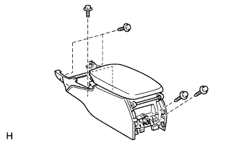 |
Remove the 4 bolts and 2 screws.
Remove the console box and then disconnect the connector.
| 34. REMOVE STEERING COLUMN ASSEMBLY |
For 3GR-FSE (Click here)
For 3UZ-FE (Click here)
| 35. REMOVE INSTRUMENT CLUSTER FINISH PANEL |
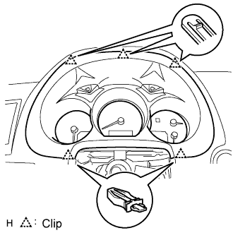 |
Using a screwdriver, detach the 5 clips.
- HINT:
- Tape the screwdriver tip before use.
Remove the cluster finish panel and then disconnect the connector.
| 36. REMOVE COMBINATION METER ASSEMBLY |
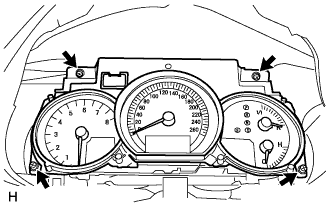 |
Remove the 4 screws.
Disconnect the connector and remove the combination meter.
| 37. REMOVE INSTRUMENT SIDE PANEL RH |
 |
Using a screwdriver, detach the 2 claws and 4 clips, and remove the side panel.
- HINT:
- Tape the screwdriver tip before use.
| 38. REMOVE INSTRUMENT SIDE PANEL LH |
 |
Using a screwdriver, detach the 2 claws and 4 clips, and remove the side panel.
- HINT:
- Tape the screwdriver tip before use.
| 39. REMOVE NO. 1 INSTRUMENT PANEL UNDER COVER SUB-ASSEMBLY |
 |
Remove the 2 screws.
Detach the 2 claws.
Remove the under cover and then disconnect the connector.
| 40. REMOVE NO. 1 INSTRUMENT PANEL SAFTY PAD SUB-ASSEMBLY |
 |
Using a screwdriver, detach the 8 clips and claw.
- HINT:
- Tape the screwdriver tip before use.
Remove the hood lock control cable from the safety pad.
Remove the safety pad.
| 41. REMOVE DRIVER SIDE KNEE AIRBAG ASSEMBLY |
Remove the 4 bolts and driver side knee airbag assembly.
 |
Disconnect the connector.
- NOTICE:
- When handling the airbag connector, take care not to damage the airbag wire harness.
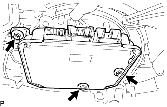
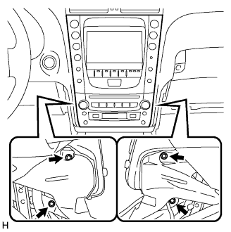
| 42. REMOVE INTEGRATION CONTROL AND PANEL ASSEMBLY |
 |
Remove the 2 screws.
Using a screwdriver, detach the 2 claws.
- HINT:
- Tape the screwdriver tip before use.
Remove the control panel and then disconnect the connector.
| 43. REMOVE NO. 2 INSTRUMENT PANEL UNDER COVER |
 |
Using a screwdriver, detach the 4 clips.
- HINT:
- Tape the screwdriver tip before use.
Disconnect the connector and clamp, and remove the under cover.
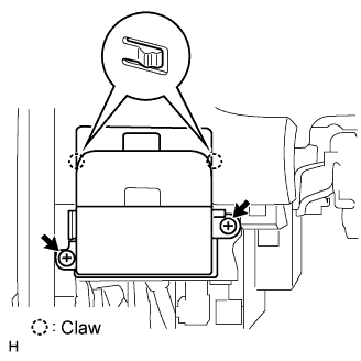
| 44. REMOVE STEERING CONTROL ECU |
Disconnect the 3 connectors from the steering control ECU.
 |
Remove the 3 screws and the steering control ECU.
 |
| 45. REMOVE FRONT PASSENGER SIDE KNEE AIRBAG ASSEMBLY |
Remove the 3 bolts and front passenger side knee airbag assembly.
 |
Disconnect the connector.
- NOTICE:
- When handling the airbag connector, take care not to damage the airbag wire harness.
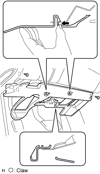
| 46. REMOVE GLOVE COMPARTMENT DOOR SUB-ASSEMBLY |
 |
Remove the 4 screws.
Detach the 2 clips and claw.
Disconnect the connector and clamp.
Remove the glove compartment door.
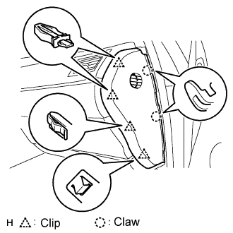
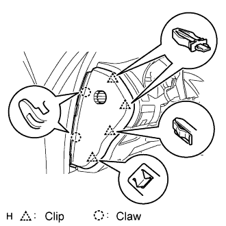
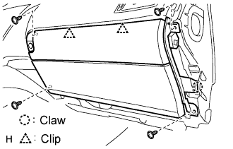
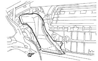
| 47. REMOVE FRONT PILLAR GARNISH RH |
- HINT:
- Use the same procedures described for the LH side.
| 48. REMOVE FRONT PILLAR GARNISH LH |
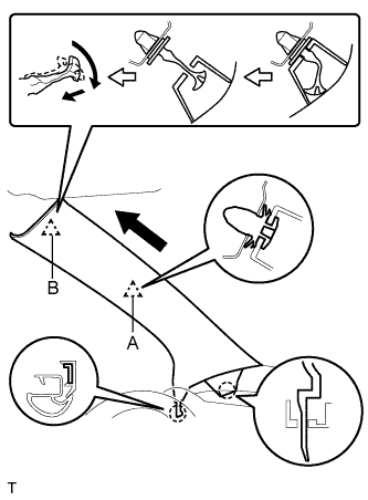 |
Detach the clip labeled A from the vehicle body. Pull the pillar garnish so that the tip of clip B locks in the pillar garnish's hole.
Using needle-nose pliers, rotate clip B 90° and remove the pillar garnish.
- HINT:
- If clip B is removed from the vehicle body or is damaged, replace it with a new one.
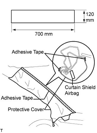
Protect the curtain shield airbag.
Thoroughly cover the airbag with a cloth or nylon sheet that is 700 mm (27.56 in.) x 120 mm (4.72 in.) and fix the ends of the cover with adhesive tape, as shown in the illustration.
- NOTICE:
- Cover the curtain shield airbag with a protective cover as soon as the front pillar garnish is removed.
 |
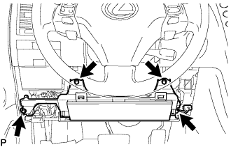
| 49. REMOVE MULTI-DISPLAY WITH RADIO RECEIVER ASSEMBLY |
Remove the 4 bolts.
 |
Pull the multi-display with radio receiver to detach the 2 clips on the backside of the multi-display.
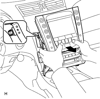 |
Disconnect the connectors and remove the multi-display with radio receiver.
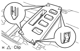
| 50. REMOVE INSTRUMENT PANEL SAFETY PAD SUB-ASSEMBLY |
w/ Navigation system:
Remove the navigation ECU.Remove the 3 bolts and navigation ECU.
Disconnect the connectors.
 |
Remove the 4 nuts and center junction block RH and LH.
Remove the 4 bolts, nut and 2 clips.
Remove the 2 bolts from the passenger airbag.
Disconnect the connectors and clamps.
Detach the 5 clips and remove the safety pad.
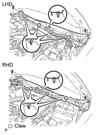
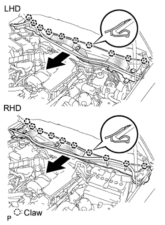
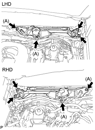
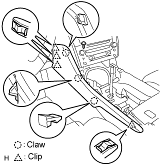
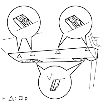
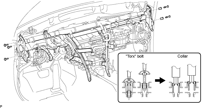
| 51. REMOVE INSTRUMENT PANEL REINFORCEMENT ASSEMBLY |
Detach the 27 clamps and disconnect the connectors. Then disconnect the wire harness.
Remove the 3 nuts, 2 bolts and disconnect the 2 junction blocks.
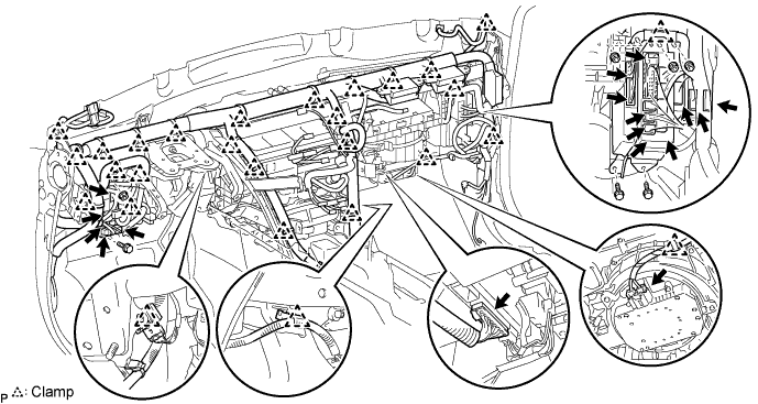
Remove the cap and bolt.
Remove the 6 bolts and 2 screws.

Using a T40 "torx" socket, remove the 5 "torx" bolts.
- HINT:
- The "torx" bolts on the passenger side can be removed with the collar for adjustment.
Using a 12 mm hexagon wrench, remove the 2 collars and instrument panel reinforcement.
| 52. REMOVE NO. 2 AIR DUCT |
Remove the screw and air duct.
 |
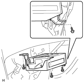
| 53. REMOVE AIR CONDITIONING AMPLIFIER ASSEMBLY |
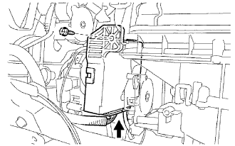 |
Disconnect the connector.
Remove the screw and A/C amplifier.
| 54. REMOVE BLOWER ASSEMBLY |
Disconnect the connector.
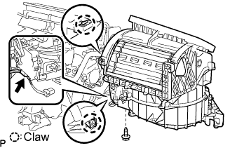 |
Remove the screw and nut.
Detach the 2 claws and remove the blower.