Air Conditioning Unit -- Installation |
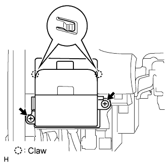
| 1. INSTALL BLOWER ASSEMBLY |
Install the blower with the 2 claws and screw.
- Torque:
- 3.0 N*m{30 kgf*cm, 27 in.*lbf}
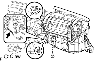 |
Connect the connector.
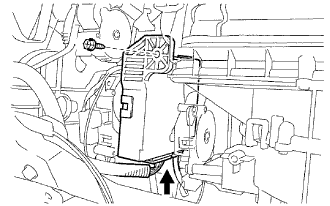
| 2. INSTALL AIR CONDITIONING AMPLIFIER ASSEMBLY |
Install the A/C amplifier with the screw and connect the connector.
 |
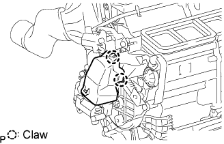
| 3. INSTALL NO. 2 AIR DUCT |
Install the duct with the screw.
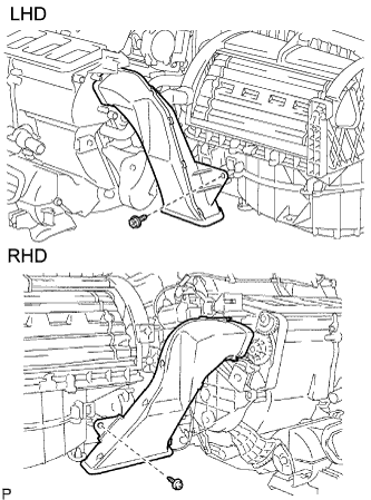 |
| 4. INSTALL FOOT DUCT UPPER (for LHD) |
Attach the 2 claws and install the foot duct.
 |
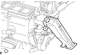
| 5. INSTALL FOOT DUCT LOWER (for LHD) |
Attach the 2 claws to install the foot duct.
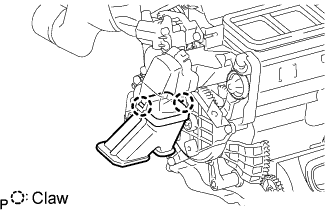 |
| 6. INSTALL NO. 1 AIR DUCT (for RHD) |
Attach the 2 claws and install the foot duct.
 |
| 7. INSTALL AIR CONDITIONING UNIT ASSEMBLY |
Install the A/C unit with the nut.
- Torque:
- 9.8 N*m{100 kgf*cm, 7 ft.*lbf}
 |
| 8. INSTALL INSTRUMENT PANEL REINFORCEMENT ASSEMBLY |
Driver side:
Using a T40 "torx" socket, install the instrument panel reinforcement with the 3 "torx" bolts.
- Torque:
- 17 N*m{173 kgf*cm, 13 ft.*lbf}
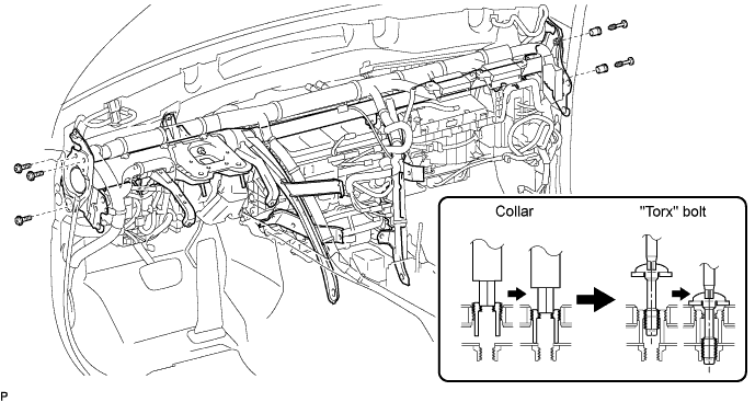
Passenger side:
Using a 12 mm hexagon wrench, install the instrument panel reinforcement with the 2 bolts.
- Torque:
- 6.0 N*m{61 kgf*cm, 53 in.*lbf}
Using a T40 "torx" socket, install the instrument panel reinforcement with the 2 "torx" bolts.
- Torque:
- 20 N*m{204 kgf*cm, 15 ft.*lbf}
Install the instrument panel reinforcement with the 6 bolts and 2 screws.
- Torque:
- :
- 9.8 N*m{100 kgf*cm, 7 ft.*lbf}for bolt A
Install the bolt and cap.

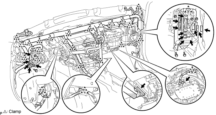
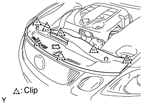
Connect the 2 connectors and attach the 27 clamps.
Install the 2 junction blocks with the 2 bolts and 3 nuts.
| 9. CONNECT TRANSPONDER KEY ECU ASSEMBLY |
Install the transponder key ECU with the screw.
 |
Attach the clamp.
| 10. INSTALL DEFROSTER LOWER NOZZLE ASSEMBLY |
Attach the 4 claws to install the defroster lower nozzle.
 |
| 11. INSTALL NO. 1 CONSOLE BOX DUCT |
Install the console box duct.
 |
| 12. INSTALL NO. 2 CONSOLE BOX DUCT |
Install the console box duct with the 2 clips.
 |
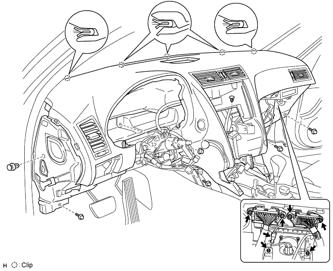
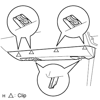
| 13. INSTALL INSTRUMENT PANEL SAFETY PAD SUB-ASSEMBLY |
Attach the 5 clips to install the safety pad.
Connect the connectors and clamps.
Install the 2 bolts to the passenger airbag.
- Torque:
- 20 N*m{204 kgf*cm, 15 ft.*lbf}
Install the 4 bolts, nut and 2 clips.
Install the center junction block RH and LH with the 4 nuts.
w/ Navigation system:
Install the navigation ECU.Connect the connector.
Install the ECU with the 3 bolts.
 |
| 14. INSTALL MULTI-DISPLAY WITH RADIO RECEIVER ASSEMBLY |
Connect the connectors.
Insert the multi-display with radio receiver and attach the 2 clips on its backside.
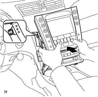 |
Install the multi-display with radio receiver with the 4 bolts.
 |
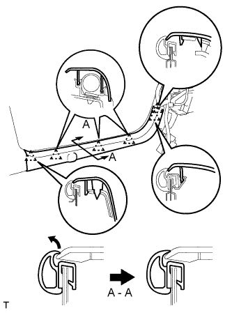
| 15. INSTALL FRONT PILLAR GARNISH LH |
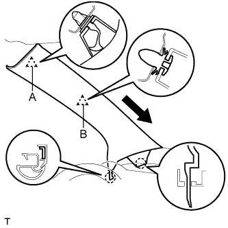 |
Attach a new clip A to the vehicle body.
Set the pillar garnish to the area labeled B. Using needle-nose pliers, install clip A to the pillar garnish and rotate it 90°.
Install the pillar garnish by attaching the claws and clip.
Pull out the folded lip of the weatherstrip.
| 16. INSTALL FRONT PILLAR GARNISH RH |
- HINT:
- Use the same procedures described for the LH side.
| 17. INSTALL GLOVE COMPARTMENT DOOR SUB-ASSEMBLY |
 |
Attach the 2 clips and claw to install the glove compartment door.
Connect the connector and clamp.
Install the 4 screws.
| 18. INSTALL FRONT PASSENGER SIDE KNEE AIRBAG ASSEMBLY |
Connect the connector.
- NOTICE:
- When handling the airbag connector, take care not to damage the airbag wire harness.
 |
Install the front passenger side knee airbag assembly with the 3 bolts.
- Torque:
- 10 N*m{102 kgf*cm, 7 ft.*lbf}
| 19. INSTALL STEERING CONTROL ECU |
Install the steering control ECU with the 3 screws.
- HINT:
- Align positioning boss (A) of the blower assembly with the hole of the steering control ECU.
- Securely engage hook (B) of the steering control ECU with the blower assembly.
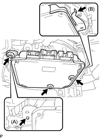 |
Connect the 3 connectors to the steering control ECU.
 |
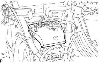
| 20. INSTALL NO. 2 INSTRUMENT PANEL UNDER COVER SUB-ASSEMBLY |
 |
Connect the connector and clamp.
Attach the 4 clips to install the under cover.
| 21. INSTALL INTEGRATION CONTROL AND PANEL ASSEMBLY |
 |
Connect the connector.
Attach the 2 claws to install the control panel.
Install the 2 screws.
| 22. INSTALL DRIVER SIDE KNEE AIRBAG ASSEMBLY |
Connect the connector.
- NOTICE:
- When handling the airbag connector, take care not to damage the airbag wire harness.
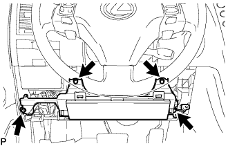 |
Install the driver side knee airbag assembly with the 4 bolts.
- Torque:
- 10 N*m{102 kgf*cm, 7 ft.*lbf}
| 23. INSTALL NO.1 INSTRUMENT PANEL SAFETY PAD SUB-ASSEMBLY |
 |
Install the hood lock control cable to the safety pad.
Attach the 8 clips and claw to install the safety pad.
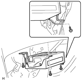
| 24. INSTALL NO. 1 INSTRUMENT PANEL UNDER COVER SUB-ASSEMBLY |
 |
Connect the connectors.
Attach the 2 claws to install the under cover.
Install the 2 screws.
| 25. INSTALL INSTRUMENT SIDE PANEL LH |
 |
Attach the 2 claws and 4 clips to install the side panel.
| 26. INSTALL INSTRUMENT SIDE PANEL RH |
 |
Attach the 2 claws and 4 clips to install the side panel.
| 27. INSTALL COMBINATION METER ASSEMBLY |
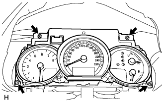 |
Connect the connector.
Install the combination meter with the 4 screws.
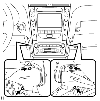
| 28. INSTALL INSTRUMENT CLUSTER FINISH PANEL SUB-ASSEMBLY |
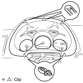 |
Connect the connector.
Attach the 5 clips to install the cluster finish panel.
| 29. INSTALL CONSOLE BOX |
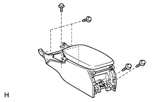 |
Connect the connector.
Install the console box with the 4 bolts and 2 screws.
| 30. INSTALL STEERING COLUMN ASSEMBLY |
For 3GR-FSE (Click here)
For 3UZ-FE (Click here)
| 31. INSTALL CONSOLE BOX REGISTER ASSEMBLY |
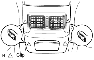 |
Attach the 4 clips to install the register.
| 32. INSTALL CONSOLE BOX PLATE |
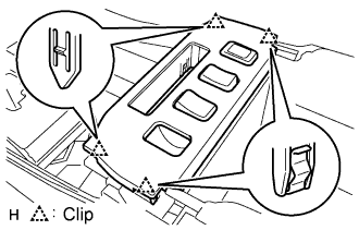 |
Connect the connector.
Attach the 4 clips to install the console box.
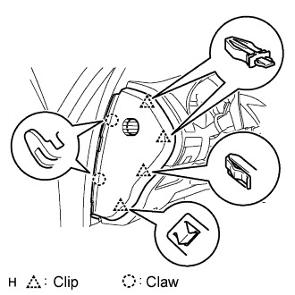
| 33. INSTALL INSTRUMENT PANEL FINISH PANEL END LH |
 |
Attach the 4 clips and 3 claws to install the finish panel end.
Install the screw.
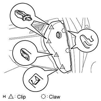
| 34. INSTALL INSTRUMENT PANEL FINISH PANEL END RH |
 |
Attach the 3 clips and 3 claws to install the finish panel end.
Install the screw.
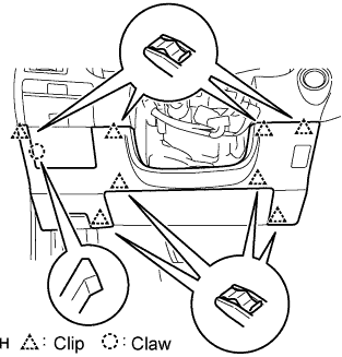
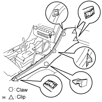
| 35. INSTALL CONSOLE UPPER PANEL ASSEMBLY |
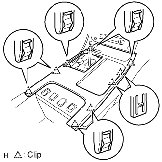 |
Connect the connector.
Attach the 9 clips to install the ash receptacle.
Install the shift lever knob and twist it in the direction indicated by the arrow.
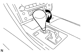 |
| 36. INSTALL FRONT CONSOLE UPPER PANEL GARNISH |
Attach the claws to install the garnish.
| 37. INSTALL HEADLIGHT DIMMER SWITCH ASSEMBLY |
 |
Install the dimmer switch with the claw as shown in the illustration.
- HINT:
- Make sure that the claw is completely engaged.
Install the dimmer switch with the clamp.
 |
Connect the connector.
| 38. INSTALL WINDSHIELD WIPER SWITCH ASSEMBLY |
 |
Attach the claw and install the wiper switch.
Connect the connector.
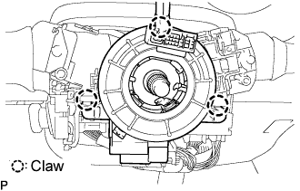
| 39. INSTALL SPIRAL CABLE WITH STEERING SENSOR |
Check that the front wheels are facing straight ahead.
Set the turn signal switch to the neutral position.
- NOTICE:
- If it is not in the neutral position, the pin of the turn signal switch may be snapped.
Engage the 3 claws and install the spiral cable with steering sensor.
- NOTICE:
- When replacing the spiral cable with a new one, remove the lock pin before installing the steering wheel assembly.
 |
Connect the connectors to the spiral cable with steering sensor.
- NOTICE:
- When handling the airbag connector, take care not to damage the airbag wire harness.
| 40. INSTALL STEERING COLUMN COVER UPPER |
For 3GR-FSE (Click here)
For 3UZ-FE (Click here)
| 41. INSTALL STEERING COLUMN COVER LOWER |
For 3GR-FSE (Click here)
For 3UZ-FE (Click here)
| 42. INSTALL STEERING WHEEL ASSEMBLY |
For 3GR-FSE (Click here)
For 3UZ-FE (Click here)
| 43. INSTALL STEERING PAD |
Support the steering pad with one hand as shown in the illustration.
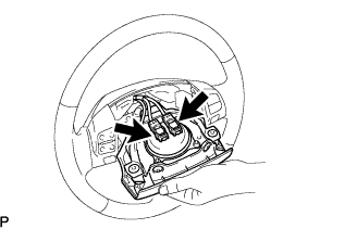 |
Connect the 2 connectors to the steering pad.
- NOTICE:
- When handling the airbag connector, take care not to damage the airbag wire harness.
Connect the horn connector.
Confirm that the circumference groove of the "torx" screw fits in the screw case, and place the steering pad onto the steering wheel assembly.
 |
Using a "torx" socket wrench (T30), tighten the 2 "torx" screws.
- Torque:
- 8.8 N*m{90 kgf*cm, 78 in.*lbf}
| 44. INSTALL NO. 3 STEERING WHEEL COVER LOWER |
| 45. INSTALL NO. 2 STEERING WHEEL COVER LOWER |
| 46. INSTALL FRONT DOOR OPENING TRIM COVER LH |
Attach the 3 claws to install the trim cover.
Pull out the folded lip of the weatherstrip.
| 47. INSTALL FRONT DOOR OPENING TRIM COVER RH |
- HINT:
- Use the same procedures described for the LH side.
| 48. INSTALL FRONT DOOR SCUFF PLATE LH |
 |
Attach the 5 claws to install the scuff plate.
Pull out the folded lip of the weatherstrip.
| 49. INSTALL FRONT DOOR SCUFF PLATE RH |
- HINT:
- Use the same procedures described for the LH side.
| 50. INSTALL HEATER WATER INLET HOSE A |
Install the water hose and attach the clip.
 |
| 51. INSTALL HEATER WATER OUTLET HOSE A |
Use the same procedures described for the water hose.
| 52. INSTALL LIQUID TUBE SUB-ASSEMBLY A |
Remove the vinyl tape attached to the tube.
Sufficiently apply compressor oil to a new O-ring and the fitting surface of the liquid tube.
- Compressor oil:
- ND-OIL 8 or equivalent
Install the O-ring on the liquid tube.
Install the liquid tube to the fitting hole.
| 53. INSTALL SUCTION PIPE SUB-ASSEMBLY |
Remove the vinyl tape attached to the pipe.
 |
Sufficiently apply compressor oil to a new O-ring and the fitting surface of the suction pipe.
- Compressor oil:
- ND-OIL 8 or equivalent
Install the O-ring on the suction pipe.
Move the hook connector in the direction indicated by the arrow in the illustration.
Insert the pipe joints into the fitting holes securely and tighten the bolt.
- Torque:
- 9.8 N*m{100 kgf*cm, 7 ft.*lbf}
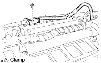
| 54. INSTALL FRONT WIPER MOTOR AND LINK ASSEMBLY |
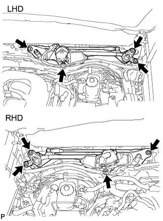 |
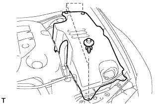
Install the wiper motor and link assembly with the 4 bolts.
- Torque:
- 5.5 N*m{56 kgf*cm, 49 in.*lbf}
Connect the connector. Then attach the 2 clamps to install the wire harness to the cowl top panel.
 |
| 55. INSTALL COWL TOP VENTILATOR LOUVER SUB-ASSEMBLY |
Push the ventilator louver in the direction indicated by the arrow in the illustration. Attach the 10 claws to install the ventilator louver.
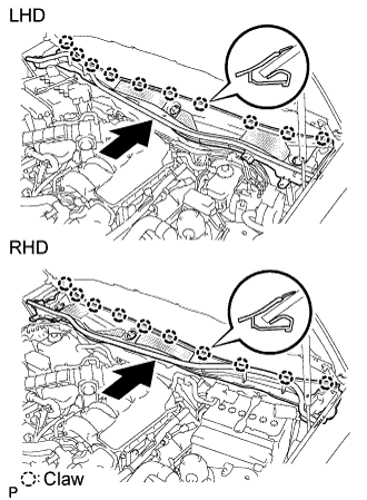 |
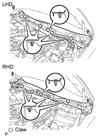
Attach the 5 claws and 2 clips to install the ventilator louver.
 |
| 56. INSTALL FRONT FENDER TO COWL SIDE SEAL LH |
Push the cowl side seal in the direction indicated by the arrow in the illustration. Attach the 2 claws to install the cowl side seal.
 |
| 57. INSTALL FRONT FENDER TO COWL SIDE SEAL RH |
- HINT:
- Use the same procedures described for the LH side.
| 58. INSTALL FRONT WIPER ARM AND BLADE ASSEMBLY LH |
 |
Stop the wiper motor at the automatic stop position.
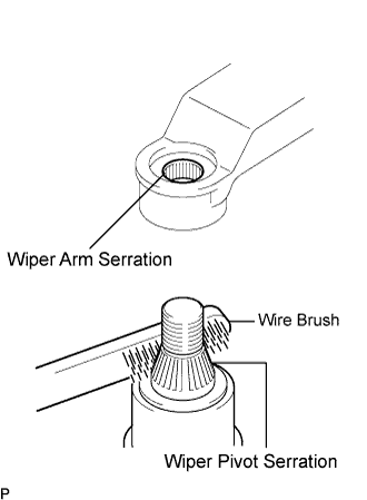
Clean the wiper arm serration with a round file or equivalent.
Clean the wiper pivot serration with a wire brush.
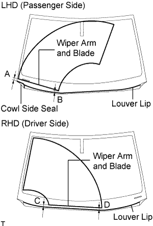
Install the wiper arm and blade with the nut. Make sure that the wiper arm and blade comes to the position shown in the illustration.
- Torque:
- 22 N*m{224 kgf*cm, 16 ft.*lbf}
- HINT:
- Hold down the wiper arm hinge with your hand while tightening the nut.
- Specification:
Area Measurement A (for LHD) 25.3 mm (0.996 in.) B (for LHD) 26.2 mm (1.031 in.) C (for RHD) 21.8 mm (0.858 in.) D (for RHD) 28.9 mm (1.138 in.)
 |
| 59. INSTALL FRONT WIPER ARM AND BLADE ASSEMBLY RH |
|
Stop the wiper motor at the automatic stop position.
Clean the wiper arm serration with a round file or equivalent.
Clean the wiper pivot serration with a wire brush.
Install the wiper arm and blade with the nut. Make sure that the wiper arm and blade comes to the position shown in the illustration.
- Torque:
- 22 N*m{224 kgf*cm, 16 ft.*lbf}
- HINT:
- Hold down the wiper arm hinge with your hand while tightening the nut.
- Specification:
Area Measurement A (for LHD) 28.9 mm (1.138 in.) B (for LHD) 21.8 mm (0.858 in.) C (for RHD) 26.2 mm (1.031 in.) D (for RHD) 25.3 mm (0.996 in.)
 |
Operate the front wipers while spraying washer fluid on the windshield glass. Make sure that the front wipers function properly and there is no interference with the vehicle body.
| 60. INSTALL ENGINE ROOM SIDE COVER LH (for LHD) |
Install the side cover with the 3 clips.
 |
| 61. INSTALL FRONT PILLAR TO FRONT SIDE SEAL SUB-ASSEMBLY LH |
 |
Attach the 3 clips to install the side seal.
| 62. INSTALL FRONT PILLAR TO FRONT SIDE SEAL SUB-ASSEMBLY RH |
- HINT:
- Use the same procedures described for the LH side.
| 63. CONNECT CABLE TO NEGATIVE BATTERY TERMINAL |
| 64. ADD ENGINE COOLANT |
- NOTICE:
- Before adding engine coolant, turn the A/C switch OFF.
Tighten all the plugs and fill the radiator with TOYOTA Super Long Life Coolant (SLLC).
- Torque:
- 12.7 N*m{130 kgf*cm, 9 ft.*lbf} for cylinder block drain cock plug
Add engine coolant.
- Specified capacity:
- 9.1 liters (9.6 US qts, 8.0 lmp. qts)
- NOTICE:
- When pressing the radiator hose:
- Wear protective gloves.
- Be careful as the radiator hose is hot.
- Keep your hands away from the radiator fan.
- HINT:
- TOYOTA vehicles are filled with TOYOTA SLLC at the factory. In order to avoid damage to the engine cooling system and other technical problems, only use TOYOTA SLLC or similar high quality ethylene glycol based non-silicate, non-amine, non-nitrite, non-borate coolant with long-life hybrid organic acid technology (coolant with long-life hybrid organic acid technology consists of a combination of low phosphates and organic acids).
- Please contact your TOYOTA dealer for further details.
- The thermostat open timing can be confirmed by pressing the inlet radiator hose by hand, and checking when the engine coolant starts to flow inside the hose.
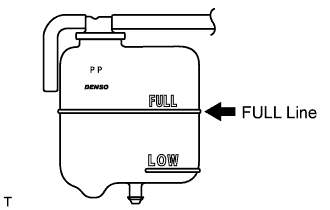
Slowly pour coolant into the radiator reservoir until it reaches the FULL line.
Press the inlet and outlet radiator hoses several times by hand, and then check the level of the coolant.
If the coolant level is low, add coolant.
Install the radiator cap and reservoir cap.
Bleed air from the cooling system.
- NOTICE:
- Before starting the engine to warm up the engine, turn the A/C switch OFF.
Warm up the engine until the thermostat opens. While the thermostat is open, circulate the coolant for several minutes.
- HINT:
- The thermostat open timing can be confirmed by pressing the inlet radiator hose by hand, and checking when the engine coolant starts to flow inside the hose.
- NOTICE:
- When pressing the radiator hoses:
- Wear protective gloves.
- Be careful as the radiator hoses are hot.
- Keep your hands away from the radiator fan.
Maintain the engine speed at 2,000 to 2,500 rpm.
Press the inlet and outlet radiator hoses several times by hand to bleed air.
- NOTICE:
- When pressing the radiator hoses:
- Wear protective gloves.
- Be careful as the radiator hoses are hot.
- Keep your hands away from the radiator fan.
Stop the engine, and wait until the engine coolant cools down to ambient temperature.
- CAUTION:
- Do not remove the radiator cap while the engine and radiator are still hot. Pressurized, hot engine coolant and steam may be released and cause serious burns.
Check the coolant level in the radiator reservoir.
If the coolant level is low, add SLLC to the radiator reservoir FULL line.
 |
| 65. CHARGE REFRIGERANT |
Perform vacuum purging using a vacuum pump.
Charge refrigerant HFC-134a (R134a).
- Standard:
- 450 +- 50 g (15.87 +- 1.76 oz.)
- SST
- 07110-58060(07117-58060,07117-58070,07117-58080,07117-58090,07117-78050,07117-88060,07117-88070,07117-88080)

- NOTICE:
- Do not operate the cooler compressor before charging refrigerant as the cooler compressor will not work properly without any refrigerant, and will overheat.
- Approximately 100 g (3.53 oz.) of refrigerant may need to be charged after bubbles disappear. The refrigerant amount should be checked by measuring its quantity, and not with the sight glass.
| 66. INSTALL COOL AIR INTAKE DUCT SEAL |
 |
Install the intake duct seal with the 7 clips.
| 67. WARM UP ENGINE |
Warm up the engine at less than 1,850 rpm for 2 minutes or more after charging the refrigerant.
- NOTICE:
- Be sure to warm up the compressor when turning the A/C switch ON after removing and installing the cooler refrigerant lines (including the compressor), to prevent damage to the compressor.
| 68. CHECK FOR ENGINE COOLANT LEAKS |
Check for engine coolant leaks (Click here).
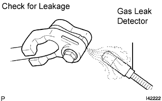
| 69. CHECK FOR LEAKAGE OF REFRIGERANT |
After recharging the refrigerant gas, check for refrigerant gas leakage using a halogen leak detector.
Perform the operation under these conditions:
- Stop the engine.
- Secure good ventilation (the gas leak detector may react to volatile gases other than refrigerant, such as evaporated gasoline or exhaust gas).
- Repeat the test 2 or 3 times.
- Make sure that some refrigerant remains in the refrigeration system. When compressor is off: approximately 392 to 588 kPa (4 to 6 kgf/cm2 57 to 85 psi)
- Stop the engine.
Using a gas leak detector, check the refrigerant line for leakage.
 |
If a gas leak is not detected on the drain hose, remove the blower motor control (blower resistor) from the cooling unit. Insert the gas leak detector sensor into the unit and perform the test.
Disconnect the connector and leave the pressure switch on for approximately 20 minutes. Bring the gas leak detector close to the pressure switch and perform the test.
| 70. PERFORM INITIALIZATION |
Perform initialization (Click here).
- NOTICE:
- Certain systems need to be initialized after disconnecting and reconnecting the cable from the negative (-) battery terminal.
| 71. CHECK SRS WARNING LIGHT |
Check the SRS warning light (Click here).