Clearance Warning Ecu (For Rhd) -- Removal |
| 1. DISCONNECT CABLE FROM NEGATIVE BATTERY TERMINAL |
- CAUTION:
- Wait at least 90 seconds after disconnecting the cable from the negative (-) battery terminal to prevent arbag and seat belt pretensioner activation.
| 2. REMOVE FRONT DOOR SCUFF PLATE LH |
Using a moulding remover, detach the 3 claws and remove the trim cover.
| 3. REMOVE FRONT DOOR OPENING TRIM COVER LH |
Using a moulding remover, detach the 3 claws and remove the trim cover.
| 4. REMOVE INSTRUMENT SIDE PANEL LH |
 |
Using a screwdriver, detach the 2 claws and 4 clips, and remove the side panel.
- HINT:
- Tape the screwdriver tip before use.
| 5. REMOVE FRONT CONSOLE UPPER PANEL GARNISH |
 |
Using a clip remover, detach the claws and remove the garnish.
- HINT:
- Tape the clip remover tip before use.
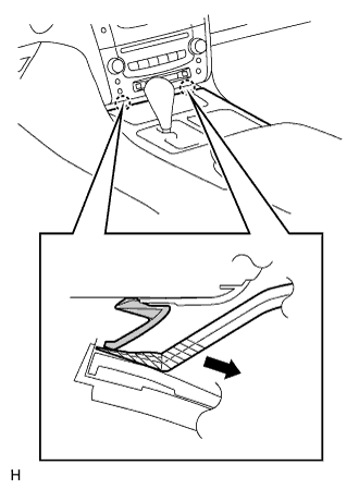
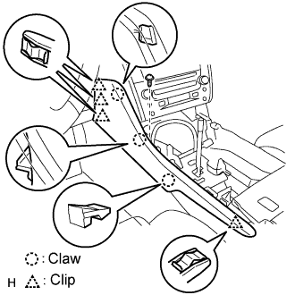
| 6. REMOVE CONSOLE UPPER PANEL ASSEMBLY |
 |
Twist the shift lever knob in the direction indicated by the arrow and remove it.
Using a screwdriver, detach the 9 clips.
- HINT:
- Tape the screwdriver tip before use.
 |
Remove the ash receptacle and then disconnect the connector.
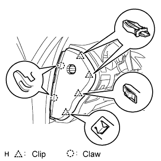
| 7. REMOVE INSTRUMENT PANEL FINISH PANEL END LH |
 |
Remove the screw.
Using a screwdriver, detach the 4 clips and 3 claws.
- HINT:
- Tape the screwdriver tip before use.
Remove the finish panel end.
| 8. REMOVE NO. 2 INSTRUMENT PANEL UNDER COVER SUB-ASSEMBLY |
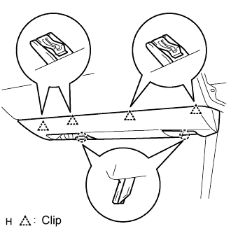 |
Using a screwdriver, detach the 4 clips.
- HINT:
- Tape the screwdriver tip before use.
Disconnect the connector and clamp, and remove the under cover.
| 9. REMOVE FRONT PASSENGER SIDE KNEE AIRBAG ASSEMBLY |
Remove the 3 bolts and front passenger side knee airbag assembly.
 |
Disconnect the connector.
- NOTICE:
- When handling the airbag connector, take care not to damage the airbag wire harness.
| 10. REMOVE GLOVE COMPARTMENT DOOR SUB-ASSEMBLY |
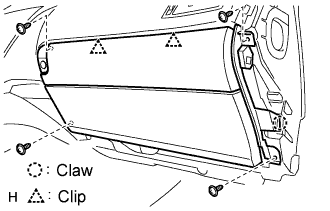 |
Remove the 4 screws.
Detach the 2 clips and claw.
Disconnect the connector and clamp.
Remove the glove compartment door.
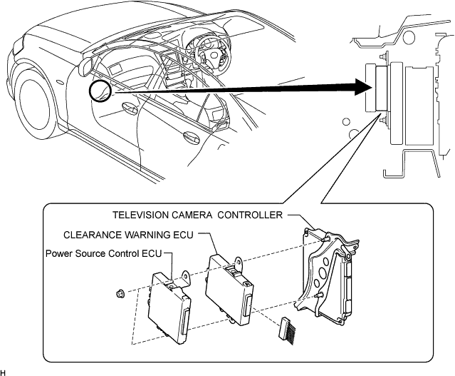
| 11. REMOVE TELEVISION CAMERA CONTROLLER |
 |
Disconnect the 2 controller connectors.
Disconnect the clearance warning ECU and power source control ECU connectors.
Remove the nut, bolt and television camera controller.
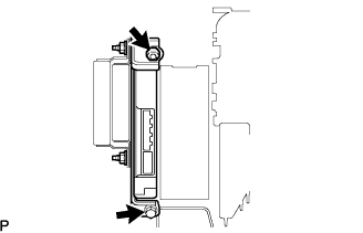
| 12. REMOVE CLEARANCE WARNING ECU ASSEMBLY |
Disconnect the clearance warning ECU and power source control ECU connectors.
Remove the 2 nuts and power source control ECU together with the clearance warning ECU.