Radio Antenna Cord -- Installation |
- HINT:
- A bolt without a torque specification is shown in the standard bolt chart (Click here).
| 1. INSTALL NO. 2 ANTENNA CORD SUB-ASSEMBLY |
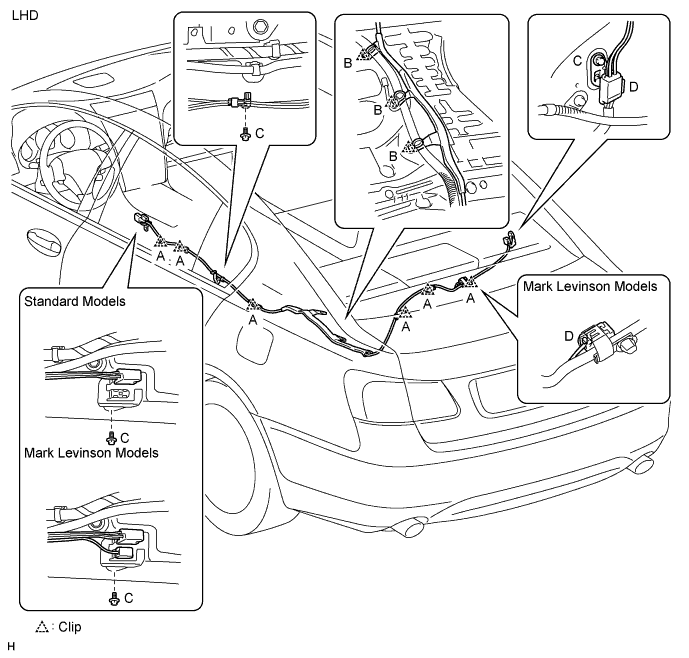
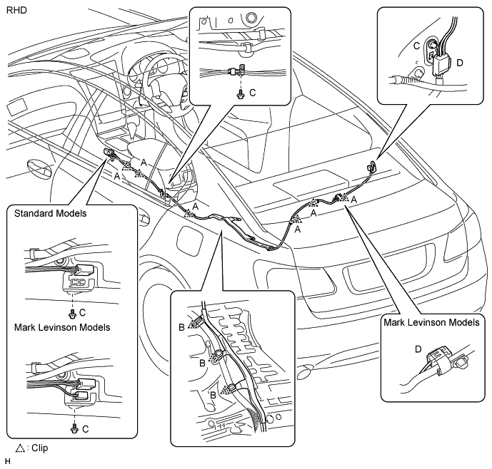
Attach the 6 clips labeled A.
Attach the antenna cord protector's 3 clips labeled B to the floor stud bolts.
Install the 3 bolts labeled C.
Connect the connectors labeled D.
| 2. INSTALL REAR SEAT SIDE GARNISH RH |
- HINT:
- Use the same procedures described for the LH side.
| 3. INSTALL REAR DOOR SCUFF PLATE RH |
- HINT:
- Use the same procedures described for the LH side.
| 4. INSTALL REAR SEATBACK ASSEMBLY |
 |
Place the seatback in the cabin.
- NOTICE:
- Be careful not to damage the vehicle body.
Install the seatback with the 4 bolts and 2 nuts.
- Torque:
- 18.1 N*m{185 kgf*cm, 13 ft.*lbf}
Install the 2 rear seat covers.
Pass the 3 seat belts through and close the cap of the 3 rear seat shoulder belt guides.
Install the floor anchor part with the bolt.
| 5. INSTALL REAR SEAT HEADREST ASSEMBLY LH AND RH |
| 6. INSTALL REAR SEAT HEADREST ASSEMBLY CENTER |
| 7. INSTALL REAR SEAT CUSHION ASSEMBLY |
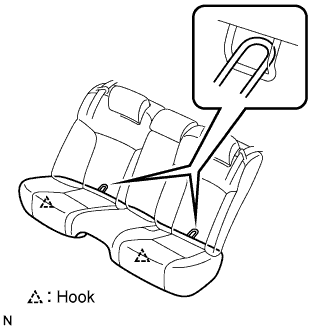 |
Attach the seat cushion's 2 rear hooks to the seatback.
Attach the seat cushion's 2 front hooks to the vehicle body.
Confirm that the seat cushion is firmly installed.
- NOTICE:
- When installing the seat cushion, make sure the seat belt buckle is not under the seat cushion.
| 8. INSTALL ANTENNA CORD SUB-ASSEMBLY |
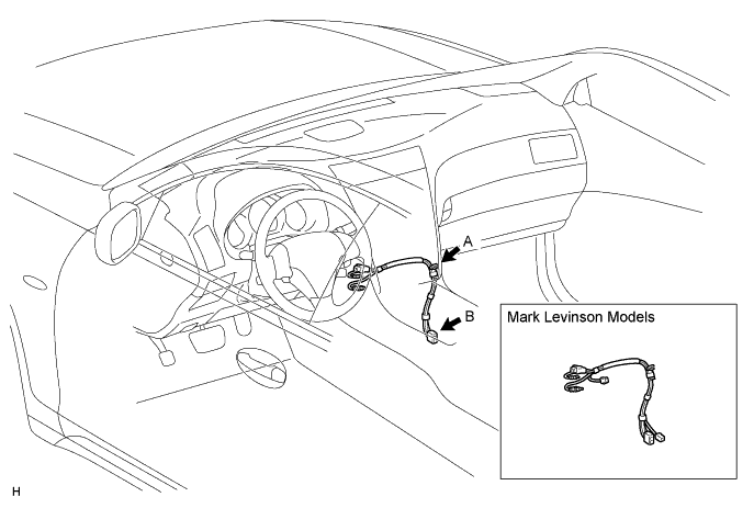
Attach the clip labeled A.
Connect the connector labeled B.
| 9. INSTALL MULTI-DISPLAY WITH RADIO RECEIVER ASSEMBLY |
Connect the connectors.
Insert the multi-display with radio receiver and attach the 2 clips on its backside.
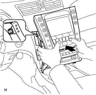 |
Install the multi-display with radio receiver with the 4 bolts.
 |
| 10. INSTALL CONSOLE BOX |
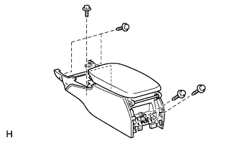 |
Connect the connector.
Install the console box with the 4 bolts and 2 screws.
| 11. INSTALL CONSOLE BOX REGISTER ASSEMBLY |
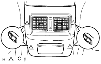 |
Attach the 4 clips to install the register.
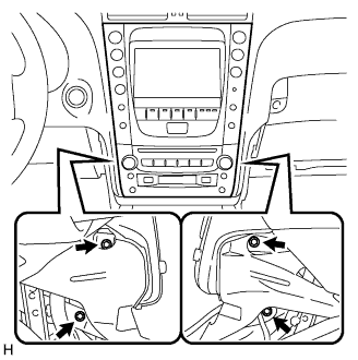
| 12. INSTALL CONSOLE BOX PLATE |
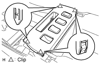 |
Connect the connector.
Attach the 4 clips to install the console box.
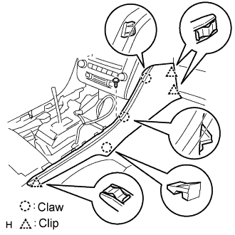
| 13. INSTALL INSTRUMENT PANEL FINISH PANEL END LH |
 |
Attach the 4 clips and 3 claws to install the finish panel end.
Install the screw.
| 14. INSTALL INSTRUMENT PANEL FINISH PANEL END RH |
 |
Attach the 3 clips and 3 claws to install the finish panel end.
Install the screw.
| 15. INSTALL CONSOLE UPPER PANEL ASSEMBLY |
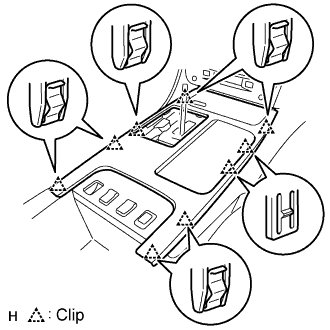 |
Connect the connector.
Attach the 9 clips to install the ash receptacle.
Install the shift lever knob and twist it in the direction indicated by the arrow.
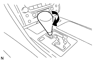 |
| 16. INSTALL FRONT CONSOLE UPPER PANEL GARNISH |
Attach the claws to install the garnish.
| 17. CONNECT CABLE TO NEGATIVE BATTERY TERMINAL |
| 18. PERFORM INITIALIZATION |
Perform initialization (Click here).
- NOTICE:
- Certain systems need to be initialized after disconnecting and reconnecting the cable from the negative (-) battery terminal.