Adaptive Variable Suspension System -- System Description |
| SYSTEM DESCRIPTION |
Absorber Control ECU
- The shock absorber damping force can be switched individually for each of the four wheels using the information from the sensors, and the set mode can be selected, by operating the absorber control switch.
- Damping force switching controls are as follows: control according to vehicle speed, which is determined by driving conditions, anti-dive control, anti-squat control, rolling control, shudder control (H∞ control), which is controlled according to vehicle movement (road surface), bumpy control, and spring-bottom vibration control (unsprung damping control). Further, there is also a VSC cooperative control for VSC operations.
- Accurate damping force control is achieved by using nonlinear H∞ control based on the current theory in shudder control. The frequency of the bumps and shudders are monitored using signals from the acceleration sensor assembly, and the frequency of unsprung resonance is monitored using signals from the wheel speed sensors to achieve smooth damping control performance commensurate with driving status.
- The shock absorber damping force can be switched individually for each of the four wheels using the information from the sensors, and the set mode can be selected, by operating the absorber control switch.
Speed Sensor Control
- A smooth ride at low speed, and operability and stability at high speed, are balanced by making optimum settings of the damping force commensurate with vehicle speed, based on wheel speed sensor information.
- A smooth ride at low speed, and operability and stability at high speed, are balanced by making optimum settings of the damping force commensurate with vehicle speed, based on wheel speed sensor information.
Anti-Dive Control
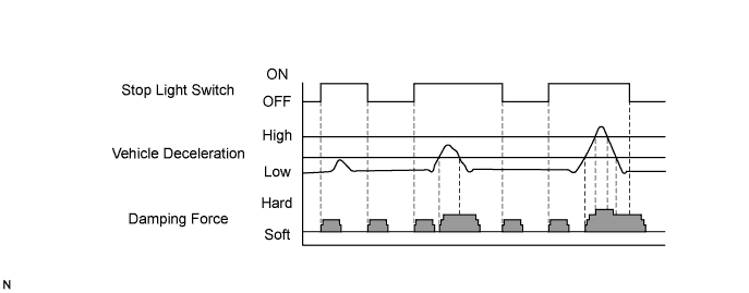
- The anti-dive control assures operability and stability, (smoothing dive due to speed changes during deceleration), by accurately controlling damping force commensurate with the chassis dive status detected during braking using speed signals from the wheels and signals from the stop light switch.
- Operability and stability during braking are assured while a smooth ride is also assured by setting the damping force to high both if deceleration G is great and when the driver has released the brake pedal.
- The anti-dive control assures operability and stability, (smoothing dive due to speed changes during deceleration), by accurately controlling damping force commensurate with the chassis dive status detected during braking using speed signals from the wheels and signals from the stop light switch.
Anti-squat Control
- Vehicle squat is reduced, and operability and stability are assured, by accurately controlling the damping force by detecting vehicle squat during acceleration using the number of engine rotations.
- Vehicle squat is reduced, and operability and stability are assured, by accurately controlling the damping force by detecting vehicle squat during acceleration using the number of engine rotations.
Rolling Control
- Excellent operability and stability during cornering are achieved by controlling the damping force commensurate with the level of the lateral acceleration calculated using the turning angle signals from the steering angle sensor and the vehicle speed signals from the wheel speed sensors.
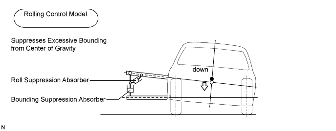
- The outer damping force of the outer and inner turnings (for all four wheels independently) is controlled by using control theory according to the rolling control model for the absorbers (for roll suppression and bound suppression), which suppress movement in two directions from a virtual point on the inner turning, as described in the diagram below. That enables to achieve excellent operability and stability, and to assure turning and tracking performance and wheel-to-ground contact by optimizing the wheel status during rotation.
- Excellent operability and stability during cornering are achieved by controlling the damping force commensurate with the level of the lateral acceleration calculated using the turning angle signals from the steering angle sensor and the vehicle speed signals from the wheel speed sensors.
Shudder Control (H∞ Control)
- If shudder in the roll and pitch directions is small, the shudder can be controlled by increasing the damping force for a specified time. If the shudder is great, the ride will lose its smoothness if the damping force only is properly increased. Consequently, to balance high damping performance and optimum ride smoothness, shudder control that applies the nonlinear H∞ control theory is used.
- Three acceleration sensor assemblies are used to detect sprung acceleration over road surface unevenness, and used to calculate the suspension stroke status by applying current control theory. The target damping force is calculated from these loads using H∞ control theory, and the damping force is then controlled for all four wheels independently.
- Damping control can be actively enhanced in the target frequency band by setting frequency weighting functions in the sprung acceleration in the shudder resonant frequency band. To control the sprung acceleration and vary the damping force to control the energy ratio of the sprung acceleration to the road surface input at the set value max.

- If the vehicle status is controlled by using shock absorber damping force only, and if the damping force varies greatly, shudder can easily occur in the sprung acceleration.
- Natural and smooth shudder control is achieved in the sprung damping, by applying nonlinear H∞ control theory.

- If shudder in the roll and pitch directions is small, the shudder can be controlled by increasing the damping force for a specified time. If the shudder is great, the ride will lose its smoothness if the damping force only is properly increased. Consequently, to balance high damping performance and optimum ride smoothness, shudder control that applies the nonlinear H∞ control theory is used.
Bumpy Control
- If the frequency between the sprung resonance and unsprung resonance (bump frequency) is detected by using signals from the acceleration sensor while driving on a rough road surface in which shudder and bumps occur simultaneously, the damping force is set comparatively low, to achieve a smooth sensation within the vehicle, without the smooth ride being damaged.
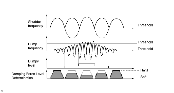
- If the frequency between the sprung resonance and unsprung resonance (bump frequency) is detected by using signals from the acceleration sensor while driving on a rough road surface in which shudder and bumps occur simultaneously, the damping force is set comparatively low, to achieve a smooth sensation within the vehicle, without the smooth ride being damaged.
Spring-Bottom Vibration Control (unsprung damping control)
- If unsprung resonance is detected by using signals from the wheel speed sensors, the unsprung resonance is controlled by increasing the damping force for a fixed period to achieve high road surface contact without the smooth ride being damaged.
- If unsprung resonance is detected by using signals from the wheel speed sensors, the unsprung resonance is controlled by increasing the damping force for a fixed period to achieve high road surface contact without the smooth ride being damaged.
VSC Operation Control (VSC cooperative control)
- The VDIM (VSC) effectiveness can be maximized by suitably switching the damping force commensurate with changes in the road surface μ and the vehicle lateral skid, using signals from the skid control ECU.
- The VDIM (VSC) effectiveness can be maximized by suitably switching the damping force commensurate with changes in the road surface μ and the vehicle lateral skid, using signals from the skid control ECU.
| DAMPING FORCE CHARACTERISTICS |
Two kinds of mode, NORMAL and SPORT, can be selected by operating the absorber control switch.
NORMAL is the mode that gives the highest priority to a comfortable ride. Damping force is lowest when driving under normal conditions.
SPORT is the mode in which damping force is set higher, even when driving under normal conditions. SPORT improves further the driving performance and stability by utilizing wider area of high damping force, even when the damping force is affected by the driving and road conditions. In this mode, by the difference in damping force between the inside and outside wheels, excessive body roll is prevented.
| FAIL-SAFE FUNCTION (Click here) |
When a failure occurs in the AVS (Adaptive Variable Suspension System) system, the absorber control indicator light comes on and AVS operation is prohibited.
| DATA LIST/ACTIVE TEST (Click here) |
Data list
According to the Data List displayed on the intelligent tester, the value and status of the switch, sensor, ECU, etc. can be read without removing parts.
Reading Data List as the first step in troubleshooting is one way to shorten labor time.Active test
Performing the Active Test using the intelligent tester allows the relay, ECU, etc. to operate without removing parts.
Performing the Active Test as the first step in troubleshooting is one way to shorten labor time.
| FUNCTION OF COMPONENTS |
| Components | Function |
| Absorber Control Switch (EMS Switch) |
|
| Steering Angle Sensor |
|
| Acceleration Sensor Assembly (Right Front) |
|
| Acceleration Sensor Assembly (Left Front) |
|
| Acceleration Sensor Assembly (Rear) |
|
| Speed Sensor (Skid Control ECU) |
|
| Absorber Control Actuator |
|
| Absorber Control ECU |
|