Meter / Gauge System Malfunction In Speedometer
Meter. Lexus Gs430, Gs300. Uzs190 Grs190
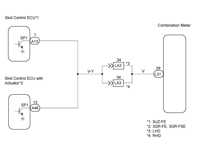
WIRING DIAGRAM
INSPECTION PROCEDURE
PERFORM ACTIVE TEST BY INTELLIGENT TESTER
READ VALUE OF INTELLIGENT TESTER
READ VALUE OF INTELLIGENT TESTER
INSPECT COMBINATION METER
CHECK HARNESS AND CONNECTOR (COMBINATION METER - SKID CONTROL ECU)
INSPECT SKID CONTROL ECU
METER / GAUGE SYSTEM - Malfunction in Speedometer |
WIRING DIAGRAM
INSPECTION PROCEDURE
| 1.PERFORM ACTIVE TEST BY INTELLIGENT TESTER |
Operate the intelligent tester according to the display and select the "Active Test".
- Combination meter:
Item
| Test Details
| Diagnostic Note
|
Speed Meter Operation
| 0 / 40 (24) / 80 (48) / 120 (72) / 160 (96) / 200 (120) / 240 (149) km/h (mph)
| -
|
- OK:
- Needle indication is normal.
| | REPLACE COMBINATION METER |
|
|
| 2.READ VALUE OF INTELLIGENT TESTER |
Operate the intelligent tester according to the display and select the "Data List".
- Combination meter:
Item
| Measurement Item / Range (Display)
| Normal Condition
| Diagnostic Note
|
Vehicle Speed Meter
| Vehicle speed / Min.: 0 km/h (0 mph), Max.: 255 km/h (158 mph)
| Almost same as actual vehicle speed (When driving)
| -
|
- OK:
- Vehicle speed displayed on the tester is almost the same as the actual vehicle speed.
| OK |
|
|
|
| REPLACE COMBINATION METER |
|
| 3.READ VALUE OF INTELLIGENT TESTER |
Operate the intelligent tester according to the display and select the "Data List".
- Skid control ECU:
Item
| Measurement Item / Range (Display)
| Normal Condition
| Diagnostic Note
|
FR WHEEL SPD
| Wheel speed sensor (FR) reading/ Min.: 0 km/h (0 mph), Max.: 326 km/h (202 mph)
| Almost same as actual vehicle speed (When driving)
| -
|
FL WHEEL SPD
| Wheel speed sensor (FL) reading/ Min.: 0 km/h (0 mph), Max.: 326 km/h (202 mph)
| Almost same as actual vehicle speed (When driving)
| -
|
RR WHEEL SPD
| Wheel speed sensor (RR) reading/ Min.: 0 km/h (0 mph), Max.: 326 km/h (202 mph)
| Almost same as actual vehicle speed (When driving)
| -
|
RL WHEEL SPD
| Wheel speed sensor (RL) reading/ Min.: 0 km/h (0 mph), Max.: 326 km/h (202 mph)
| Almost same as actual vehicle speed (When driving)
| -
|
- OK:
- Vehicle speed displayed on the tester is almost the same as the actual vehicle speed.
| 4.INSPECT COMBINATION METER |
Check the input signal waveform.
Remove the combination meter with the connector still connected.
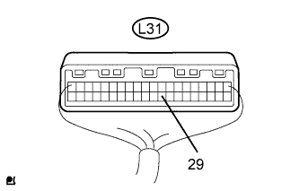
Connect the oscilloscope to the terminals L31-29 and body ground.
Start the engine.
Check the signal waveform of the connector.
Item
| Condition
|
Tool Setting
| 5 V/DIV, 20 msec/DIV.
|
Vehicle Condition
| Driving at approx. 20 km/h (12 mph)
|
- OK:
- As shown in the illustration
- HINT:
- As vehicle speed increases, the cycle of the signal waveform narrows.
| OK |
|
|
|
| REPLACE COMBINATION METER |
|
| 5.CHECK HARNESS AND CONNECTOR (COMBINATION METER - SKID CONTROL ECU) |
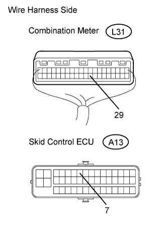
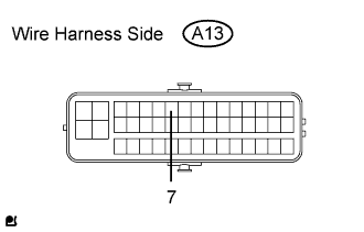
3UZ-FE:
Disconnect the L31 meter connector.
Disconnect the A13 meter connector.
Measure the resistance of the wire harness side connectors.
- Standard resistance:
Tester Connection
| Condition
| Specified Condition
|
L31-29 - A13-7
| Always
| Below 1 Ω
|
L31-29 - Body ground
| Always
| 10 kΩ or higher
|
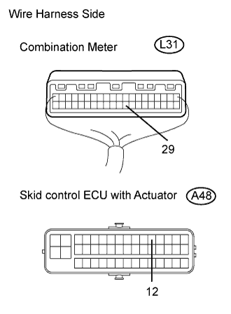
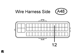
3GR-FE, 3GR-FSE:
Disconnect the L31 meter connector.
Disconnect the A48 meter connector.
Measure the resistance of the wire harness side connectors.
- Standard resistance:
Tester Connection
| Condition
| Specified Condition
|
L31-29 - A48-12
| Always
| Below 1 Ω
|
L31-29 - Body ground
| Always
| 10 kΩ or higher
|
| | REPAIR OR REPLACE HARNESS AND CONNECTOR |
|
|
| 6.INSPECT SKID CONTROL ECU |
3UZ-FE:
Disconnect the A13 ECU connector.
Measure the voltage of the wire harness side connector.
- Standard voltage:
Tester Connection
| Condition
| Specified Condition
|
A13-7 - Body ground
| Engine switch on (IG)
| 10 to 14 V
|
3GR-FE, 3GR-FSE:
Disconnect the A48 ECU connector.
Measure the voltage of the wire harness side connector.
- Standard Voltage:
Tester Connection
| Condition
| Specified Condition
|
A48-12 - Body ground
| Engine switch on (IG)
| 10 to 14 V
|
| | REPLACE COMBINATION METER |
|
|