Water Pump -- Removal |
| 1. DISCONNECT CABLE FROM NEGATIVE BATTERY TERMINAL |
- CAUTION:
- Wait at least 90 seconds after disconnecting the cable from negative (-) battery terminal to prevent airbag and seat belt pretensioner activation.
| 2. REMOVE ENGINE UNDER COVER |
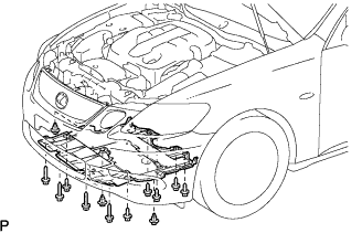 |
Using a clip remover, remove the 3 clips.
Remove the 10 screws and under cover.
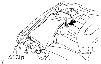
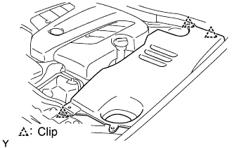
| 3. REMOVE V-BANK COVER SUB-ASSEMBLY |
Remove the 2 bolts and cover.
| 4. REMOVE COOL AIR INTAKE DUCT SEAL |
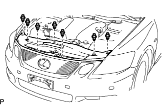 |
Using a clip remover, remove the 7 clips and duct seal.
| 5. REMOVE ENGINE ROOM SIDE COVER RH |
Remove the nut, 2 clips and side cover.
 |
| 6. REMOVE ENGINE ROOM SIDE COVER LH |
Remove the 3 clips and side cover.
 |
| 7. REMOVE NO. 1 AIR CLEANER INLET |
Remove the bolt and inlet.
| 8. REMOVE INTAKE AIR CONNECTOR PIPE |
Disconnect the air hose and No. 1 ventilation hose.
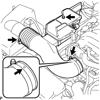 |
Loosen the 2 hose clamps and remove the intake air connector.
| 9. REMOVE AIR CLEANER ASSEMBLY |
Disconnect the MAF meter connector and clamp.
Remove the 3 bolts and air cleaner assembly.
| 10. DISCONNECT RADIATOR HOSE INLET |
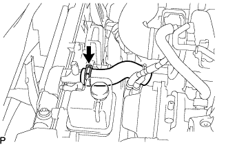 |
Disconnect the hose inlet.
| 11. DISCONNECT RADIATOR HOSE OUTLET |
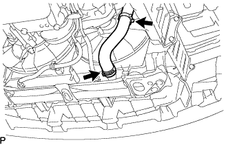 |
Disconnect the hose outlet.
| 12. DISCONNECT NO. 1 OIL COOLER INLET TUBE |
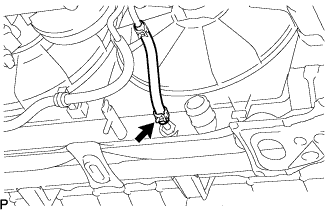 |
Disconnect the tube from the radiator.
| 13. DISCONNECT NO. 1 OIL COOLER OUTLET TUBE |
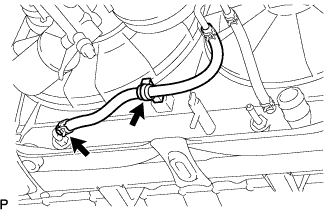 |
Disconnect the tube from the radiator.
Detach the tube from the radiator's clamp.
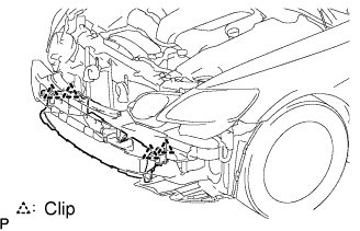
| 14. REMOVE FRONT BUMPER COVER |
Using a clip remover, remove the 2 clips.
- HINT:
- Put protective tape under the front fender.
Remove the 6 screws and 5 bolts.
 |
Pull the bumper cover to detach the 3 claws on the LH side.
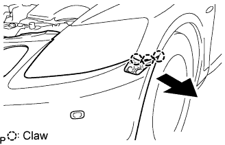 |
Pull the bumper cover to detach the 3 claws on the RH side and remove the bumper cover.
w/ Clearance sonar system:
Disconnect the ultrasonic sensor connector.
| 15. REMOVE RADIATOR SUPPORT OPENING COVER |
 |
Remove the 4 clips and cover.
| 16. REMOVE HOOD LOCK CONTROL CABLE COVER |
 |
Remove the 3 screws.
Detach the claw and remove the cable cover.
| 17. REMOVE HOOD LOCK ASSEMBLY |
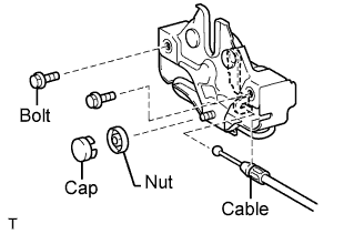 |
Disconnect the hood lock control cable.
Remove the cap.
Remove the 2 bolts and nut.
Remove the hood lock.
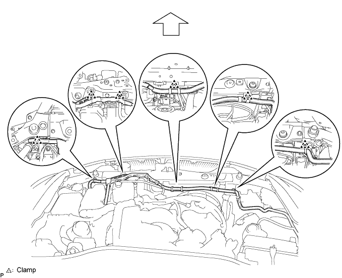
| 18. REMOVE UPPER RADIATOR SUPPORT SUB-ASSEMBLY |
Using a clip remover, detach the 6 clamps and remove the wire harness.
Disconnect the connectors.
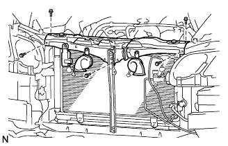 |
Remove the 5 bolts and radiator support.
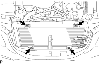
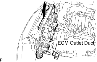
| 19. REMOVE RADIATOR ASSEMBLY |
Disconnect the wire harness from the cooling fan ECU.
Remove the 4 bolts.
 |
Detach the ECM outlet duct.
 |
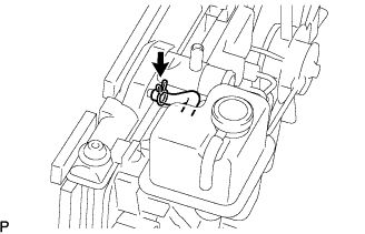
Remove the radiator from the engine room.
Disconnect the reservoir hose.
 |
Detach the 3 claws and remove the fan.
 |
Remove the 2 radiator support cushions and 2 radiator lower supports from the radiator.
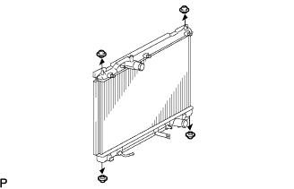 |
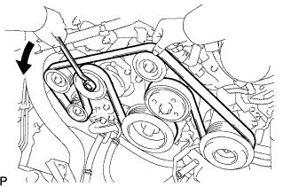
| 20. REMOVE V-RIBBED BELT |
Loosen the belt tension by turning the belt tensioner counterclockwise, and remove the belt.
- HINT:
- The tension pulley has a left hand thread.
 |
| 21. REMOVE GENERATOR ASSEMBLY |
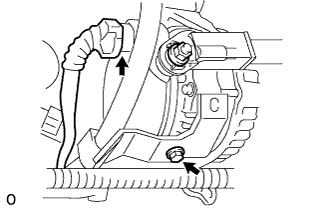 |
Disconnect the generator connector.
Remove the bolt and bracket.
Detach the rubber cap, and then remove the nut and battery cable.
Remove the bolt and ground cable.
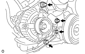 |
Remove the bolt, 2 nuts and generator.
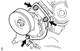
| 22. REMOVE COMPRESSOR ASSEMBLY |
 |
Disconnect the connector.
Remove the 3 bolts, nut and bracket.
Remove the compressor.
| 23. REMOVE V-RIBBED BELT TENSIONER ASSEMBLY |
Remove the bolt, 2 nuts and belt tensioner.
 |
| 24. REMOVE NO. 2 IDLER PULLEY SUB-ASSEMBLY |
Remove the bolt, cover plate and pulley.
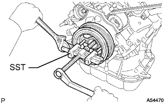
| 25. REMOVE CRANKSHAFT DAMPER SUB-ASSEMBLY |
Using SST, remove the damper bolt.
- SST
- 09213-70011
09330-00021
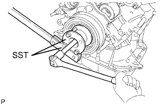 |
Using SST, remove the damper.
- SST
- 09950-50013(09951-05010,09952-05010,09953-05010,09953-05020,09954-05021)
 |
| 26. DISCONNECT OIL COOLER PIPE |
Remove the cap nut and the bolt.
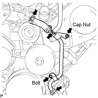 |
Disconnect the oil cooler pipe from the timing belt cover.
Disconnect the 3 water by-pass hoses from the oil cooler pipe.
| 27. REMOVE NO. 3 TIMING BELT COVER SUB-ASSEMBLY LH |
Disconnect the engine wire from the 2 wire clamps.
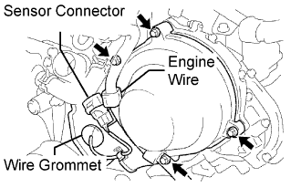 |
Disconnect the camshaft position sensor connector.
Disconnect the camshaft position sensor wire from the wire clamp on the timing belt cover.
Remove the wire grommet from the timing belt cover.
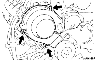
Remove the 4 bolts.
Disconnect the timing belt cover from the timing plate and camshaft bearing cap.
Disconnect the wire clamp for the sensor from the timing belt cover.
Remove the connector holder from the sensor connector.
Remove the timing belt cover.
| 28. REMOVE NO. 3 TIMING BELT COVER SUB-ASSEMBLY RH |
Remove the cap nut, 3 bolts, timing belt cover and gasket.
 |
| 29. REMOVE NO. 2 TIMING BELT COVER SUB-ASSEMBLY |
Remove the 2 bolts and timing belt cover.
 |
| 30. REMOVE IDLER PULLEY ASSEMBLY |
Remove the 2 bolts, 2 nuts and idler pulley.
 |
| 31. REMOVE NO. 1 TIMING BELT COVER |
Remove the 4 bolts and cover.
| 32. REMOVE TIMING GEAR COVER SPACER |
Remove the cover spacer and gasket.
| 33. REMOVE NO. 1 CRANKSHAFT POSITION SENSOR |
Disconnect the sensor connector.
 |
Remove the bolt and sensor.
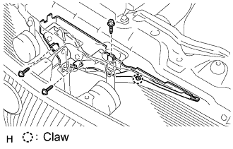
| 34. REMOVE NO. 1 TIMING BELT TENSIONER ASSEMBLY |
Remove the 2 bolts and tensioner.
| 35. REMOVE NO. 1 CRANKSHAFT POSITION SENSOR PLATE |
Remove the plate.
| 36. REMOVE TIMING BELT |
If planning to reuse the belt, check the installation marks on the timing belt.
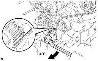
Check that there are 3 installation marks on the belt by turning the crankshaft as shown in the illustration.
- If the installation marks have disappeared, place new installation marks on the belt before removing each part.
- If the installation marks have disappeared, place new installation marks on the belt before removing each part.
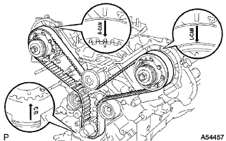 |
Set the No. 1 cylinder to approximately 50° BTDC/compression.
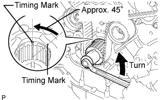
Using the crankshaft damper bolt, turn the crankshaft to align the timing marks of the crankshaft timing pulley and oil pump body.
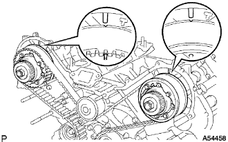
Check that the timing marks of the camshaft timing pulleys and timing belt plates are aligned.
- If not, turn the crankshaft 1 revolution (360°).
- If not, turn the crankshaft 1 revolution (360°).
Using the crankshaft damper bolt, turn the crankshaft counterclockwise by approximately 45°.
- NOTICE:
- With the timing belt disengaged, the crankshaft damper must be at the correct angle to avoid damage in a later step.
 |
Alternately loosen the 2 bolts. Then remove the 2 bolts, belt tensioner and dust boot.
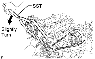
Using SST, loosen the tension between the camshaft timing pulley (RH bank) and crankshaft timing pulley by slightly turning the camshaft timing pulley (RH bank) counterclockwise.
- SST
- 09960-10010(09962-01000,09963-00350)
 |
Disconnect the belt from the No. 1 timing belt idler, and remove the belt.
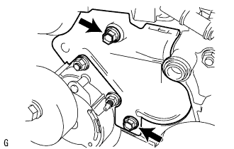
| 37. REMOVE WATER INLET HOUSING |
 |
Remove the 2 bolts and water inlet housing.
Remove the O-ring from the inlet housing.
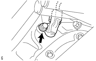
| 38. REMOVE NO. 2 TIMING BELT IDLER SUB-ASSEMBLY |
Remove the bolt, cover plate and pulley.
| 39. REMOVE WATER PUMP ASSEMBLY |
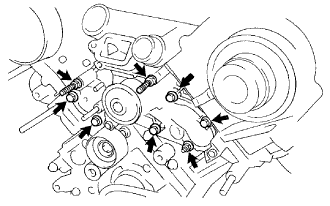 |
Remove the 5 bolts, 2 stud bolts and nut.
Using a screwdriver, remove the water pump and gasket.
 |
Remove the O-ring.