Intake Manifold -- Installation |
| 1. INSTALL INTAKE MANIFOLD SUB-ASSEMBLY |
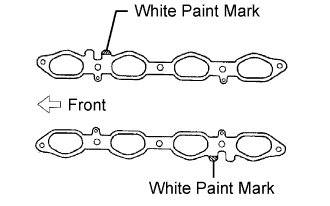
Set 2 new gaskets on the cylinder head.
- HINT:
- Make sure the white paint marks are facing upward.
 |
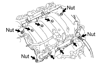
Install the intake manifold to the gasket and cylinder head with the 6 bolts and 4 nuts.
- Torque:
- 18 N*m{184 kgf*cm, 13 ft.*lbf}
 |
Connect the 8 injector connectors.
| 2. CONNECT NO. 2 FUEL PIPE SUB-ASSEMBLY |
Connect the No. 2 fuel pipe (Click here).
| 3. CONNECT ENGINE WIRE |
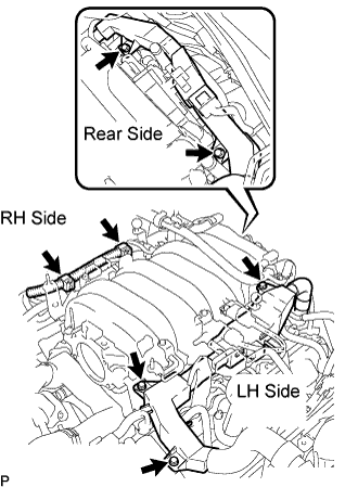 |
Install the wire protector (LH side) with the 3 bolts.
Install the 2 wire clamps on the engine wire (RH side) to the brackets on the RH delivery pipe.
Install the engine wire protector (rear side) to the rear water by-pass joint and RH cylinder head with the 2 bolts.
| 4. INSTALL NO. 3 V-BANK COVER BRACKET |
Install the bracket to the manifold with the bolt, as shown in E in the illustration below.
- Torque:
- 7.5 N*m{76 kgf*cm, 66 in.*lbf}
Connect the connector.
| 5. INSTALL NO. 2 V-BANK COVER BRACKET |
Install the bracket to the manifold with the bolt, as shown in D in the illustration below.
- Torque:
- 7.5 N*m{76 kgf*cm, 66 in.*lbf}
| 6. INSTALL VACUUM SWITCHING VALVE ASSEMBLY (for EVAP) |
Install the bracket of the VSV to the manifold with the bolt, as shown in C in the illustration below.
- Torque:
- 18 N*m{184 kgf*cm, 13 ft.*lbf}
Connect the vacuum hose to the VSV, as shown in C in the illustration below.
Connect the connector to the VSV, as shown in C in the illustration below.
| 7. INSTALL V-BANK COVER BRACKET |
Install the bracket to the manifold with the bolt, as shown in B in the illustration below.
- Torque:
- 7.5 N*m{76 kgf*cm, 66 in.*lbf}
| 8. INSTALL NO. 4 V-BANK COVER BRACKET |
Install the bracket to the manifold with the 2 nuts, as shown in A in the illustration below.
- Torque:
- 18 N*m{184 kgf*cm, 13 ft.*lbf}

| 9. INSTALL THROTTLE BODY ASSEMBLY |
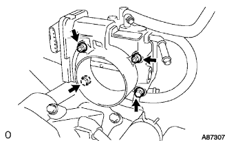
Install a new gasket and the throttle body with the 2 bolts and 2 nuts.
- Torque:
- 18 N*m{184 kgf*cm, 13 ft.*lbf}
 |
Connect the 2 water by-pass hoses.
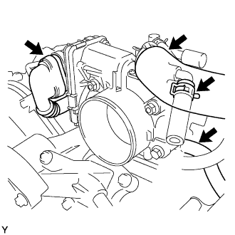 |
Connect the connector and wire.
Connect the PCV hose.
| 10. INSTALL INTAKE AIR CONNECTOR PIPE |
Install the connector pipe with the bolt and 2 hose clamps.
- Torque:
- 4.0 N*m{41 kgf*cm, 35 ft.*lbf} for hose clamps
- 5.0 N*m{51 kgf*cm, 44 ft.*lbf} for bolt
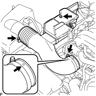 |
Connect the air hose and No. 1 ventilation hose.
| 11. CONNECT CABLE TO NEGATIVE BATTERY TERMINAL |
| 12. CHECK FOR FUEL LEAKS |
Check for fuel leaks (Click here).
| 13. ADD ENGINE COOLANT |
Tighten the radiator drain cock plug by hand.
Tighten the 2 cylinder block drain cock plugs.
- Torque:
- 12.7 N*m{130 kgf*cm, 9 ft.*lbf}
Add engine coolant.
- HINT:
- Add engine coolant until coolant overflows from the vent plug.
- Specified capacity:
- 11.0 liters (11.7 US qts, 9.7 lmp. qts)
- HINT:
- TOYOTA vehicles are filled with TOYOTA SLLC at the factory. In order to avoid damage to the engine cooling system and other technical problems, only use TOYOTA SLLC or similar high quality ethylene glycol based non-silicate, non-amine, non-nitrite, non-borate coolant with long-life hybrid organic acid technology (coolant with long-life hybrid organic acid technology consists of a combination of low phosphates and organic acids).
- Please contact your TOYOTA dealer for further details.
Install the vent plug.
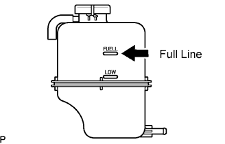
Slowly pour coolant into the radiator reservoir until it reaches the FULL line.
Press the inlet and outlet radiator hoses several times by hand, and then check the level of the coolant.
If the coolant level is low, add coolant.
Install the radiator cap.
Bleed air from the cooling system.
Warm up the engine until the thermostat opens. While the thermostat is open, circulate the coolant for several minutes.
- HINT:
- Adjust the air conditioner set temperature to MAX (HOT).
Maintain the engine speed at 2,000 to 2,500 rpm.
Press the inlet and outlet radiator hoses several times by hand to bleed air.
- NOTICE:
- When pressing the radiator hoses:
- Wear protective gloves.
- Be careful as the radiator hoses are hot.
- Keep your hands away from the radiator fan.
Stop the engine, and wait until the engine coolant cools down to ambient temperature.
- CAUTION:
- Do not remove the radiator cap while the engine and radiator are still hot. Pressurized, hot engine coolant and steam may be released and cause serious burns.
Check the coolant level in the radiator reservoir.
If the coolant level is low, add SLLC to the radiator reservoir FULL line.
 |
| 14. CHECK FOR COOLANT LEAKS |
Check for engine coolant leaks (Click here).
| 15. INSTALL V-BANK COVER SUB-ASSEMBLY |
Install the cover with the 2 nuts.
- Torque:
- 5.0 N*m{51 kgf*cm, 44 in.*lbf}
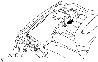
| 16. INSTALL ENGINE ROOM SIDE COVER LH |
Install the side cover with the 3 clips.
 |
| 17. INSTALL ENGINE ROOM SIDE COVER RH |
Install the side cover with the 2 clips and nut.
 |
| 18. INSTALL AIR CLEANER INLET |
Install the inlet with the bolt.
- Torque:
- 5.0 N*m{51 kgf*cm, 44 in.*lbf}
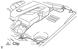
| 19. INSTALL COOL AIR INTAKE DUCT SEAL |
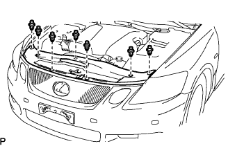 |
Install the duct seal with the 7 clips.
| 20. PERFORM INITIALIZATION |
Perform initialization (Click here).
- NOTICE:
- Certain systems need to be initialized after disconnecting and reconnecting the cable from the negative (-) battery terminal.