Lighting. Lexus Gs430, Gs300. Uzs190 Grs190
DESCRIPTION
WIRING DIAGRAM
INSPECTION PROCEDURE
CHECK OPERATION OF TURN SIGNAL LIGHT
PERFORM ACTIVE TEST BY INTELLIGENT TESTER
INSPECT FUSE (TURN-HAZ, LH-IG)
CHECK WIRE HARNESS (TURN SIGNAL FLASHER - BATTERY AND BODY GROUND)
CHECK WIRE HARNESS (TURN SIGNAL FLASHER - COWL SIDE JUNCTION BLOCK LH)
REPLACE TURN SIGNAL FLASHER
REPLACE FRONT TURN SIGNAL LIGHT BULB (TURN LH OR TURN RH)
CHECK WIRE HARNESS (TURN SIGNAL FLASHER - HEADLIGHT ASSEMBLY (TURN LH OR TURN RH) - BODY GROUND)
REPLACE TURN SIGNAL LIGHT BULB (FRONT SIDE LH OR FRONT SIDE RH)
CHECK WIRE HARNESS (TURN SIGNAL FLASHER - TURN SIGNAL LIGHT (FRONT SIDE LH OR FRONT SIDE RH) - BODY GROUND)
REPLACE REAR COMBINATION LIGHT BULB (TURN LH OR TURN RH)
CHECK WIRE HARNESS (TURN SIGNAL FLASHER - REAR COMBINATION LIGHT (TURN LH OR TURN RH) - BODY GROUND)
LIGHTING SYSTEM - Turn Signal Light Circuit |
DESCRIPTION
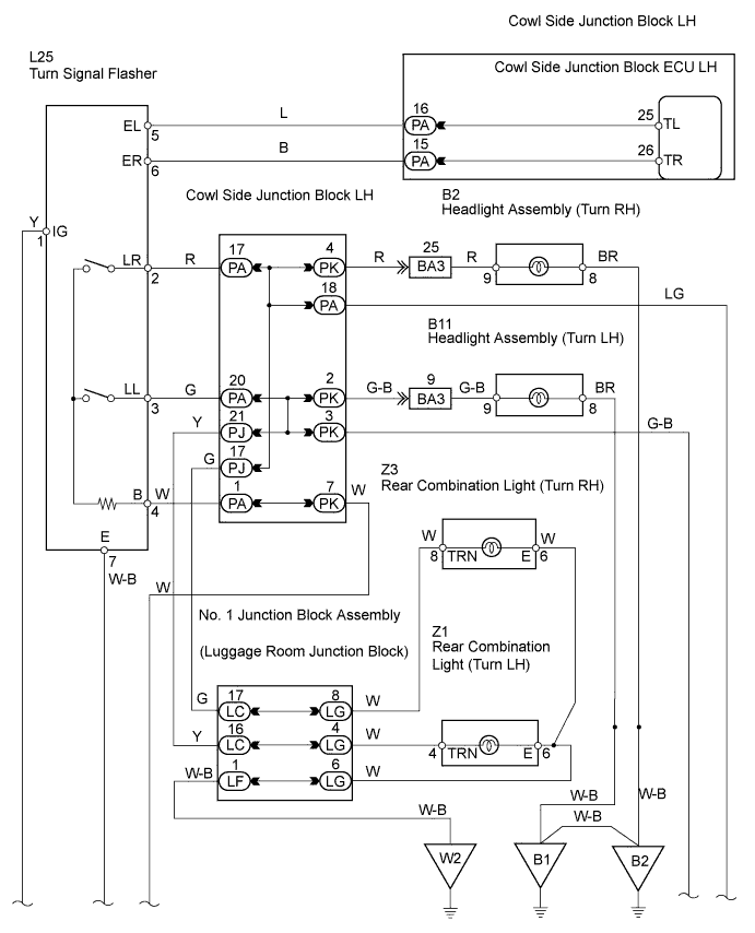
Receiving the signal of the turn signal switch from the cowl side junction block ECU LH, the cowl side junction block ECU LH makes the turn signal light come on.The cowl side junction block ECU LH activates the flasher relay while the theft deterrent system gives the warning and turns on the turn signal light and the hazard warning light.
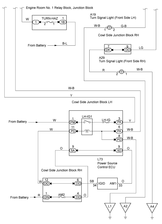
WIRING DIAGRAM
INSPECTION PROCEDURE
| 1.CHECK OPERATION OF TURN SIGNAL LIGHT |
When the turn signal light switch is operated, check that the appropriate turn signal light flashes.
- Result:
Result
| Proceed to
|
All lights do not flash
| A
|
Headlight assembly (turn LH or turn RH) does not flash
| B
|
Turn signal light (front side LH or front side RH) does not flash
| C
|
Rear combination light (LH or RH) does not flash
| D
|
| 2.PERFORM ACTIVE TEST BY INTELLIGENT TESTER |
Select the Active Test, use the intelligent tester to generate a control command, and then check that the turn signal light flashes.
- Cowl side junction block ECU LH:
Item
| Test Details
| Diagnostic Note
|
Turn Lamp RH
| Turn signal light operation ON / OFF
| -
|
Turn Lamp LH
| Turn signal light operation ON / OFF
| -
|
- OK:
- Turn signal light flashes.
| OK |
|
|
|
| PROCEED TO NEXT CIRCUIT INSPECTION SHOWN IN PROBLEM SYMPTOMS TABLE |
|
| 3.INSPECT FUSE (TURN-HAZ, LH-IG) |
Remove the LH-IG fuse from the cowl side junction block LH.
Remove the TURN-HAZ fuse from the engine room No. 1 junction block.
Measure the resistance of the fuses.
- Standard resistance:
- Below 1 Ω
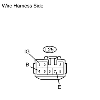
| 4.CHECK WIRE HARNESS (TURN SIGNAL FLASHER - BATTERY AND BODY GROUND) |
Disconnect the L25 flasher connector.
Measure the voltage and resistance of the wire harness side connector.
- Standard voltage:
Tester Connection
| Condition
| Specified Condition
|
L25-1 (IG) - Body ground
| Engine switch on (IG)
| 10 to 14 V
|
L25-4 (B) - Body ground
| Always
| 10 to 14 V
|
- Standard resistance:
Tester Connection
| Specified Condition
|
L25-7 (E) - Body ground
| Below 1 Ω
|
| | REPAIR OR REPLACE HARNESS AND CONNECTOR |
|
|
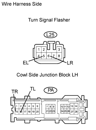
| 5.CHECK WIRE HARNESS (TURN SIGNAL FLASHER - COWL SIDE JUNCTION BLOCK LH) |
Disconnect the L25 flasher connector.
Disconnect the PA junction block cnnector.
Measure the resistance of the wire harness side connectors.
- Standard resistance:
Tester Connection
| Specified Condition
|
L25-5 (EL) - PA-16 (TL)
| Below 1 Ω
|
L25-6 (ER) - PA-15 (TR)
| Below 1 Ω
|
L25-5 (EL) or PA-16 (TL) - Body ground
| 10 kΩ or higher
|
L25-6 (ER) or PA-15 (TR) - Body ground
| 10 kΩ or higher
|
| | REPAIR OR REPLACE HARNESS AND CONNECTOR |
|
|
| 6.REPLACE TURN SIGNAL FLASHER |
Temporarily replace the turn signal flasher with a new or normally functioning one.
Check that the turn signal flasher operates.
- OK:
- Front turn signal light bulb (turn LH) flashes.
| NG |
|
|
|
| PROCEED TO NEXT CIRCUIT INSPECTION SHOWN IN PROBLEM SYMPTOMS TABLE |
|
| 7.REPLACE FRONT TURN SIGNAL LIGHT BULB (TURN LH OR TURN RH) |
Temporarily replace the front turn signal light bulb (turn LH or turn RH) with a new or normally functioning one.
Check that the front turn signal light bulb (turn LH or turn RH) flashes.
- OK:
- Front turn signal light bulb (turn LH or turn RH) flashes.
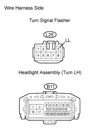
| 8.CHECK WIRE HARNESS (TURN SIGNAL FLASHER - HEADLIGHT ASSEMBLY (TURN LH OR TURN RH) - BODY GROUND) |
Check the wire harness between the headlight (turn LH) and turn signal flasher, and the headlight (turn LH) and body ground.
Disconnect the L25 flasher connector.
Disconnect the B11 headlight connector.
Measure the resistance of the wire harness side connectors.
- Standard resistance:
Tester Connection
| Specified Condition
|
L25-3 (LL) - B11-9
| Below 1 Ω
|
L25-3 (LL) or B11-9 - Body ground
| 10 kΩ or higher
|
B11-8 - Body ground
| Below 1 Ω
|
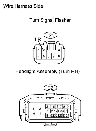
Check the wire harness between the headlight (turn RH) and turn signal flasher, and the headlight (turn RH) and body ground.
Disconnect the L25 flasher connector.
Disconnect the B2 headlight connector.
Measure the resistance of the wire harness side connectors.
- Standard resistance:
Tester Connection
| Specified Condition
|
L25-2 (LR) - B2-9
| Below 1 Ω
|
L25-2 (LR) or B2-9 - Body ground
| 10 kΩ or higher
|
B2-8 - Body ground
| Below 1 Ω
|
| | REPAIR OR REPLACE HARNESS AND CONNECTOR |
|
|
| OK |
|
|
|
| PROCEED TO NEXT CIRCUIT INSPECTION SHOWN IN PROBLEM SYMPTOMS TABLE |
|
| 9.REPLACE TURN SIGNAL LIGHT BULB (FRONT SIDE LH OR FRONT SIDE RH) |
Temporarily replace the turn signal light bulb (front side LH or front side RH) with a new or normally functioning one.
Check that the turn signal light bulb (front side LH or front side RH) flashes.
- OK:
- Turn signal light bulb (front side LH or front side RH) flashes.
| 10.CHECK WIRE HARNESS (TURN SIGNAL FLASHER - TURN SIGNAL LIGHT (FRONT SIDE LH OR FRONT SIDE RH) - BODY GROUND) |
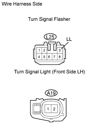
Check the wire harness between the turn signal light (front side LH) and turn signal flasher, and the turn signal light (front side LH) and body ground.
Disconnect the L25 flasher connector.
Disconnect the A19 turn signal light connector.
Measure the resistance of the wire harness side connectors.
- Standard resistance:
Tester Connection
| Specified Condition
|
L25-3 (LL) - A19-2
| Below 1 Ω
|
L25-3 (LL) or A19-2 - Body ground
| 10 kΩ or higher
|
A19-1 - Body ground
| Below 1 Ω
|
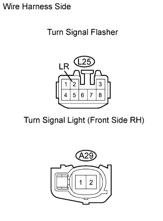
Check the wire harness between the turn signal light (front side RH) and turn signal flasher, and the turn signal light (front side RH) and body ground.
Disconnect the L25 flasher connector.
Disconnect the A29 turn signal light connector.
Measure the resistance of the wire harness side connectors.
- Standard resistance:
Tester Connection
| Specified Condition
|
L25-2 (LR) - A29-2
| Below 1 Ω
|
L25-2 (LR) or A29-2 - Body ground
| 10 kΩ or higher
|
A29-1 - Body ground
| Below 1 Ω
|
| | REPAIR OR REPLACE HARNESS AND CONNECTOR |
|
|
| OK |
|
|
|
| PROCEED TO NEXT CIRCUIT INSPECTION SHOWN IN PROBLEM SYMPTOMS TABLE |
|
| 11.REPLACE REAR COMBINATION LIGHT BULB (TURN LH OR TURN RH) |
Temporarily replace the rear combination light bulb (turn LH or turn RH) with a new or normally functioning one.
Check that the rear combination light bulb (turn LH or turn RH) flashes.
- OK:
- Rear combination light bulb (turn LH or turn RH) flashes.
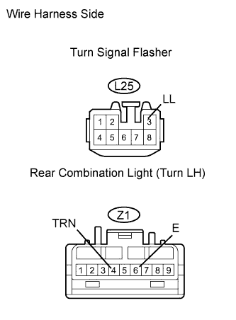
| 12.CHECK WIRE HARNESS (TURN SIGNAL FLASHER - REAR COMBINATION LIGHT (TURN LH OR TURN RH) - BODY GROUND) |
Check the wire harness between the rear combination light (turn LH) and turn signal flasher, and the rear combination light (turn LH) and body ground.
Disconnect the L25 flasher connector.
Disconnect the Z1 combination light connector.
Measure the resistance of the wire harness side connectors.
- Standard resistance:
Tester Connection
| Specified Condition
|
L25-3 (LL) - Z1-4 (TRN)
| Below 1 Ω
|
L25-3 (LL) or Z1-4 (TRN) - Body ground
| 10 kΩ or higher
|
Z1-6 (E) - Body ground
| Below 1 Ω
|
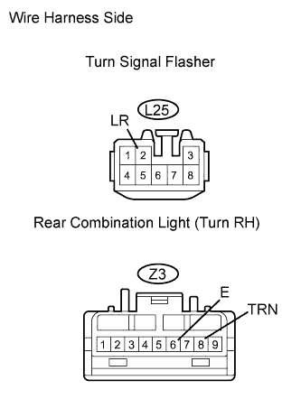
Check the wire harness between the rear combination light (turn RH) and turn signal flasher, and the rear combination light (turn RH) and body ground.
Disconnect the L25 flasher connector.
Disconnect the Z3 combination light connector.
Measure the resistance of the wire harness side connectors.
- Standard resistance:
Tester Connection
| Specified Condition
|
L25-2 (LR) - Z3-8 (TRN)
| Below 1 Ω
|
L25-2 (LR) or Z3-8 (TRN) - Body ground
| 10 kΩ or higher
|
Z3-6 (E) - Body ground
| Below 1 Ω
|
| | REPAIR OR REPLACE HARNESS AND CONNECTOR |
|
|
| OK |
|
|
|
| PROCEED TO NEXT CIRCUIT INSPECTION SHOWN IN PROBLEM SYMPTOMS TABLE |
|