Lighting System Door Courtesy Switch Circuit
Lighting. Lexus Gs430, Gs300. Uzs190 Grs190
DESCRIPTION
WIRING DIAGRAM
INSPECTION PROCEDURE
READ VALUE OF INTELLIGENT TESTER
INSPECT DOOR COURTESY SWITCH (DRIVER SIDE)
CHECK WIRE HARNESS (DOOR COURTESY SWITCH (DRIVER SIDE) - MULTIPLEX NETWORK BODY ECU)
INSPECT DOOR COURTESY SWITCH (PASSENGER SIDE)
CHECK WIRE HARNESS (DOOR COURTESY SWITCH (PASSENGER SIDE) - MULTIPLEX NETWORK BODY ECU)
INSPECT DOOR COURTESY SWITCH (REAR LH OR REAR RH)
CHECK WIRE HARNESS (DOOR COURTESY SWITCH (REAR LH OR REAR RH) - COWL SIDE JUNCTION BLOCK RH OR MULTIPLEX NETWORK BODY ECU)
LIGHTING SYSTEM - Door Courtesy Switch Circuit |
DESCRIPTION
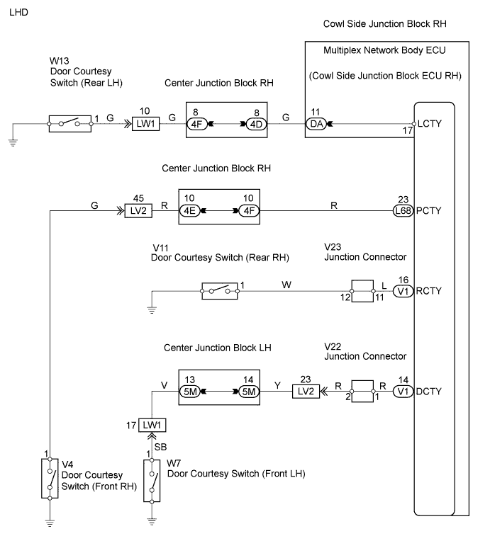
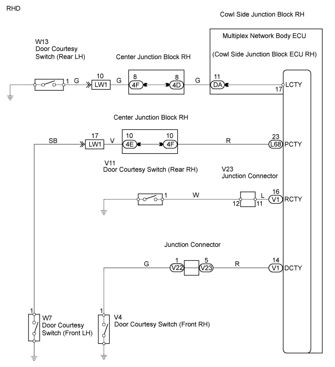
The cowl side junction block ECU RH detects the condition of each door courtesy switch and sends a signal to each door ECU via the multiplex communication circuit.
WIRING DIAGRAM
INSPECTION PROCEDURE
- HINT:
- The procedure is the same for each door courtesy switch circuit. First, inspect the suspected door courtesy switch circuit.
| 1.READ VALUE OF INTELLIGENT TESTER |
Check the Data List for proper functioning of the courtesy switch.
- Multiplex network body ECU:
Item
| Measurement Item / Display (Range)
| Normal Condition
| Diagnostic Note
|
D Door Curtesy SW
| Driver side courtesy switch / ON or OFF
| ON: Driver side door is open
OFF: Driver side door is closed
| -
|
P Door Curtesy SW
| Passenger side courtesy switch / ON or OFF
| ON: Passenger side door is open
OFF: Passenger side door is closed
| -
|
Rr Door Curtesy SW
| Rear (LH or RH) courtesy switch / ON or OFF
| ON: Rear door (LH or RH) is open
OFF: Rear door (LH or RH) is closed
| -
|
- OK:
- Condition sign can be displayed.
- Result:
Result
| Proceed to
|
OK
| A
|
Driver side door courtesy switch does not operate
| B
|
Front passenger side door courtesy switch does not operate
| C
|
Both rear door courtesy switches do not operate
| D
|
| A |
|
|
|
| PROCEED TO NEXT CIRCUIT INSPECTION SHOWN IN PROBLEM SYMPTOMS TABLE |
|
| 2.INSPECT DOOR COURTESY SWITCH (DRIVER SIDE) |
Inspection (Click here)- OK:
- Door courtesy light switch is normal.
| | REPLACE DOOR COURTESY SWITCH (DRIVER SIDE) |
|
|
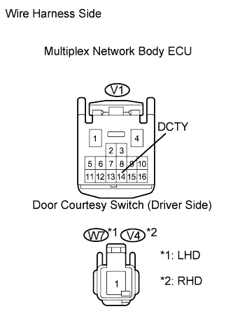
| 3.CHECK WIRE HARNESS (DOOR COURTESY SWITCH (DRIVER SIDE) - MULTIPLEX NETWORK BODY ECU) |
Disconnect the V1 ECU connector.
Disconnect the W7*1 or V4*2 switch connector.
Measure the resistance of the wire harness side connectors.
- Standard resistance:
LHDTester Connection
| Specified Condition
|
V1-14 (DCTY) - W7-1
| Below 1 Ω
|
V1-14 (DCTY) or W7-1 - Body ground
| 10 kΩ or higher
|
RHDTester Connection
| Specified Condition
|
V1-14 (DCTY) - V4-1
| Below 1 Ω
|
V1-14 (DCTY) or V4-1 - Body ground
| 10 kΩ or higher
|
| | REPAIR OR REPLACE HARNESS AND CONNECTOR |
|
|
| OK |
|
|
|
| PROCEED TO NEXT CIRCUIT INSPECTION SHOWN IN PROBLEM SYMPTOMS TABLE |
|
| 4.INSPECT DOOR COURTESY SWITCH (PASSENGER SIDE) |
Inspection (Click here)- OK:
- Door courtesy light switch is normal.
| | REPLACE DOOR COURTESY SWITCH (PASSENGER SIDE) |
|
|
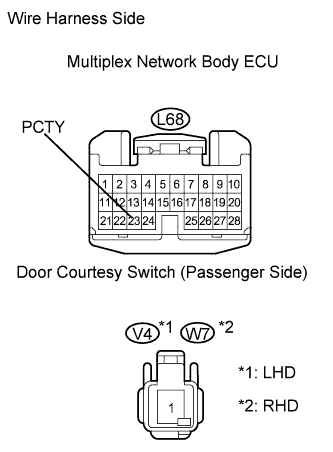
| 5.CHECK WIRE HARNESS (DOOR COURTESY SWITCH (PASSENGER SIDE) - MULTIPLEX NETWORK BODY ECU) |
Disconnect the L68 ECU connector.
Disconnect the V4*1 or W7*2 switch connector.
Measure the resistance of the wire harness side connectors.
- Standard resistance:
LHDTester Connection
| Specified Condition
|
L68-23 (PCTY) - V4-1
| Below 1 Ω
|
L68-23 (PCTY) or V4-1 - Body ground
| 10 kΩ or higher
|
RHDTester Connection
| Specified Condition
|
L68-23 (PCTY) - W7-1
| Below 1 Ω
|
L68-23 (PCTY) or W7-1 - Body ground
| 10 kΩ or higher
|
| | REPAIR OR REPLACE HARNESS AND CONNECTOR |
|
|
| OK |
|
|
|
| PROCEED TO NEXT CIRCUIT INSPECTION SHOWN IN PROBLEM SYMPTOMS TABLE |
|
| 6.INSPECT DOOR COURTESY SWITCH (REAR LH OR REAR RH) |
Inspection (Click here)- OK:
- Door courtesy light switch is normal.
| | REPLACE DOOR COURTESY SWITCH (REAR LH OR REAR RH) |
|
|
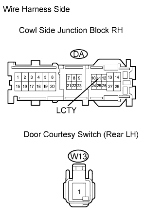
| 7.CHECK WIRE HARNESS (DOOR COURTESY SWITCH (REAR LH OR REAR RH) - COWL SIDE JUNCTION BLOCK RH OR MULTIPLEX NETWORK BODY ECU) |
Check the wire harness between the cowl side junction block RH and door courtesy switch (rear LH).
Disconnect the DA junction block connector.
Disconnect the W13 switch connector.
Measure the resistance of the wire harness side connectors.
- Standard resistance:
Tester Connection
| Specified Condition
|
DA-11 (LCTY) - W13-1
| Below 1 Ω
|
DA-11(LCTY) or W13-1 - Body ground
| 10 kΩ or higher
|
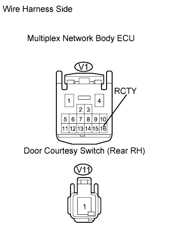
Check the wire harness between the multiplex network body ECU and door courtesy switch (rear RH).
Disconnect the V1 ECU connector.
Disconnect the V11 switch connector.
Measure the resistance of the wire harness side connectors.
- Standard resistance:
Tester Connection
| Specified Condition
|
V1-16 (RCTY) - V11-1
| Below 1 Ω
|
V1-16 (RCTY) or V11-1 - Body ground
| 10 kΩ or higher
|
| | REPAIR OR REPLACE HARNESS AND CONNECTOR |
|
|
| OK |
|
|
|
| PROCEED TO NEXT CIRCUIT INSPECTION SHOWN IN PROBLEM SYMPTOMS TABLE |
|