Dtc P1340 Camshaft Position Sensor A (Bank 1 Sensor 2)
Engine. Lexus Gs430, Gs300. Uzs190 Grs190
DESCRIPTION
MONITOR DESCRIPTION
WIRING DIAGRAM
INSPECTION PROCEDURE
INSPECT CAMSHAFT POSITION SENSOR
CHECK WIRE HARNESS (CAMSHAFT POSITION SENSOR - ECM)
CHECK SENSOR INSTALLATION
CHECK VALVE TIMING
DTC P1340 Camshaft Position Sensor "A" (Bank 1 Sensor 2) |
DTC P1341 Camshaft Position Sensor "A" (Bank 1 Sensor 2 ) |
DESCRIPTION
The camshaft position sensor, like the crankshaft position sensor, consists of a coil, a magnet and an iron core wrapped in copper wire. The camshaft has a tooth and the camshaft position sensor is installed so that it can detect the tooth passing by. When the camshaft rotates and the tooth passes by the camshaft position sensor, the magnet on the camshaft position sensor creates a magnetic field and voltage is generated in the copper wire. When the camshaft makes one full rotation, voltage will be generated in the camshaft position sensor once. The crankshaft position sensor is basically the same. When the crankshaft makes one rotation, its 34 teeth pass by the crankshaft position sensor and voltage is generated 34 times. The camshaft rotates at half the speed of the crankshaft. Therefore, the camshaft position sensor generates voltage once in the time the crankshaft makes 2 rotations. The ECM detects generation of these voltages to indicate the cylinder.DTC No.
| DTC Detection Condition
| Trouble Area
|
P1340
| No camshaft position sensor signal to ECM during cranking (2 trip detection logic)
| - Open or short in camshaft position sensor circuit
- Camshaft position sensor
- Camshaft timing gear
- ECM
|
P1340
| No camshaft position sensor signal to ECM in appropriate timing with 600 rpm or more (misalignment of crankshaft/camshaft) (1 trip detection logic)
| - Open or short in camshaft position sensor circuit
- Camshaft position sensor
- Camshaft timing gear
- ECM
|
P1341
| While crankshaft rotates twice, camshaft position sensor signal is input to ECM 12 times or more (1 trip detection logic)
| - Open or short in camshaft position sensor circuit
- Camshaft position sensor
- Camshaft timing gear
- ECM
|
MONITOR DESCRIPTION
If there is no signal from the camshaft position sensor even though the engine is turning, or if the rotation of the camshaft and the crankshaft is not synchronized, the ECM interprets this as a malfunction of the sensor. This monitor runs for 5 seconds (the first 5 seconds of engine idle) after the engine is started.
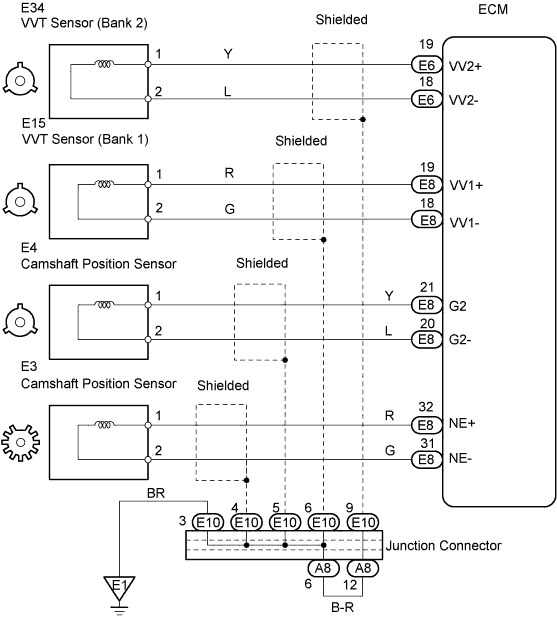
WIRING DIAGRAM
INSPECTION PROCEDURE
Camshaft position sensor.
Crankshaft position sensor.
Item
| Content
|
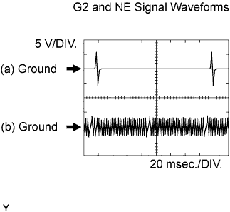
Tester Connection
| (a) G2 (E8-21) - G2- (E8-20)
(b) NE+ (E8-32) - NE- (E8-31)
|
Tester Range
| 5 V/DIV, 20 msec./DIV
|
Condition
| Idle after engine warmed-up
|
- NOTICE:
- The wavelength becomes shorter as the engine rpm increases.
- HINT:
- Read freeze frame data using the intelligent tester. Freeze frame data records the engine conditions when a malfunction is detected. When troubleshooting, freeze frame data can help determine if the vehicle was running or stopped, if the engine was warmed up or not, if the air-fuel ratio was LEAN or RICH, and other data from the time the malfunction occurred.
- DTC P1340 indicates a malfunction related to the camshaft position sensor (+) circuit.
- DTC P1341 indicates a malfunction related to the camshaft position sensor (-) circuit.
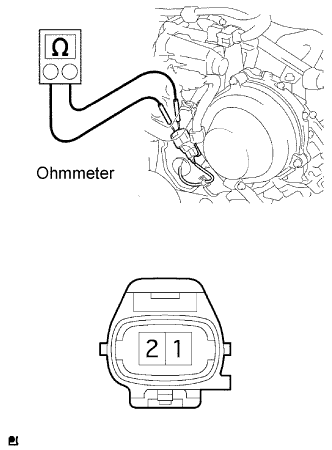
| 1.INSPECT CAMSHAFT POSITION SENSOR |
Disconnect the E4 sensor connector.
Measure the resistance of the sensor.
- Standard resistance:
Tester Connection
| Condition
| Specified Condition
|
1 - 2
| Cold
| 835 to 1,400 Ω
|
1 - 2
| Hot
| 1,600 to 1,645 Ω
|
- NOTICE:
- In the above section, the terms "cold" and "hot" refer to the temperature of the coils. "Cold" means approximately -10 to 50°C (14 to 212°F). "Hot" means approximately 50 to 100°C (122 to 212°F).
| | REPLACE CAMSHAFT POSITION SENSOR |
|
|
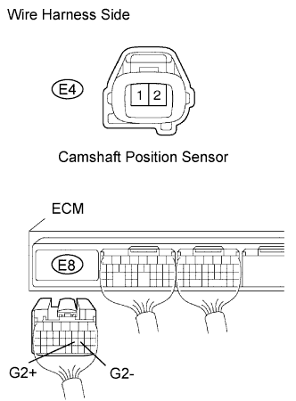
| 2.CHECK WIRE HARNESS (CAMSHAFT POSITION SENSOR - ECM) |
Disconnect the E4 camshaft position sensor connector.
Disconnect the E8 ECM connector.
Measure the resistance of the wire harness side connectors.
- Standard resistance:
Tester Connection
| Specified Condition
|
E4-1 - E8-21 (G2)
| Below 1 Ω
|
E4-2 - E8-20 (G2-)
| Below 1 Ω
|
E4-1 or E8-21 (G2) - Body ground
| 10 kΩ or higher
|
E4-2 or E8-20 (G2-) - Body ground
| 10 kΩ or higher
|
| | REPAIR OR REPLACE HARNESS AND CONNECTOR |
|
|
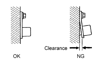
| 3.CHECK SENSOR INSTALLATION |
Check the sensor installation.
- OK:
- Sensor is installed correctly.
| | SECURELY REINSTALL SENSOR |
|
|
Remove the engine cover.
Remove the drive belt.
Remove the timing belt cover LH and RH.
Turn the crankshaft to align the matchmarks of the crankshaft.
Align the notch of the crankshaft pulley with the "0" position.
Confirm whether the matchmarks of the camshaft pulley and cylinder head cover are facing each other.
If the matchmarks are not facing each other, turn the crankshaft clockwise by 360°. Confirm again if the matchmarks are facing each other.
- OK:
- The matchmarks of the camshaft pulley and the cylinder head cover face each other when the notch of the crankshaft pulley is in the "0" position.