CHECK OTHER DTC OUTPUT (IN ADDITION TO DTC P0136, P0138, P0139, P0156, P0158, P0159)
READ DATA LIST (HEATED OXYGEN SENSOR (SENSOR 2) VOLTAGE)
INSPECT HEATED OXYGEN SENSOR (HEATER RESISTANCE)
INSPECT INTEGRATION RELAY (EFI MAIN)
CHECK WIRE HARNESS (HEATED OXYGEN SENSOR (SENSOR 2) - ECM)
PERFORM CONFIRMATION DRIVING PATTERN
READ OUTPUT DTC (DTC P0136 OR P0156 IS OUTPUT AGAIN)
READ DATA LIST (HEATED OXYGEN SENSOR (SENSOR 2) VOLTAGE)
CHECK WIRE HARNESS (CHECK FOR SHORT)
READ OUTPUT DTC (DTC P0138, P0139, P0158, OR P0159 IS OUTPUT AGAIN)
DTC P0136 Oxygen Sensor Circuit Malfunction (Bank 1 Sensor 2) |
DTC P0138 Oxygen Sensor Circuit High Voltage (Bank 1 Sensor 2) |
DTC P0139 Oxygen Sensor Circuit Slow Response (Bank 1 Sensor 2) |
DTC P0156 Oxygen Sensor Circuit Malfunction (Bank 2 Sensor 2) |
DTC P0158 Oxygen Sensor Circuit High Voltage (Bank 2 Sensor 2) |
DTC P0159 Oxygen Sensor Circuit Slow Response (Bank 2 Sensor 2) |
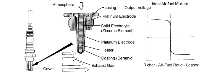
DESCRIPTION
The heated oxygen sensor is used to monitor oxygen concentration in the exhaust gas. For optimum catalytic converter operation, the air-fuel mixture must be maintained near the ideal stoichiometric air-fuel ratio. The heated oxygen sensor output voltage changes suddenly in the vicinity of the stoichiometric air-fuel ratio. The ECM adjusts the fuel injection time so that the air-fuel ratio is nearly stoichiometric. The heated oxygen sensor generates a voltage between 0.1 and 0.9 V in response to oxygen concentration in the exhaust gas.If the oxygen concentration in the exhaust gas increases, the air-fuel ratio is called LEAN. The heated oxygen sensor voltage drops below 0.45 V, which informs the ECM of the LEAN condition.
If oxygen is not in the exhaust gas, the air-fuel ratio is called RICH. The heated oxygen sensor voltage increases above 0.45 V, which informs the ECM of the RICH condition.
| DTC No. | DTC Detection Condition | Trouble Area |
| P0136 P0138 P0139 P0156 P0158 P0159 |
|
|
MONITOR DESCRIPTION
The ECM monitors the heated oxygen sensor (sensor 2) to make sure:- The heated oxygen sensor voltage does not remain RICH (above 0.5 V) or LEAN (below 0.4 V) while the vehicle is accelerating and decelerating for 4 to 8 minutes. If the voltage remains either RICH or LEAN, the ECM interprets this as a malfunction, illuminates the MIL and sets a DTC.
- The heated oxygen sensor voltage does not remain at less than 0.05 V for a long time while the vehicle is running. If the voltage remains at less than 0.05 V for a long time, the ECM interprets this as a malfunction, illuminates the MIL and sets a DTC.
- The sensor's voltage drops to below 0.2 V (extremely LEAN status) immediately when the vehicle decelerates and fuel-cut is operating. If the voltage does not drop to below 0.2 V, the ECM determines that the sensor's response feature has deteriorated, illuminates the MIL and sets a DTC.
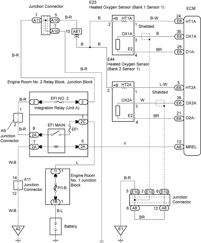
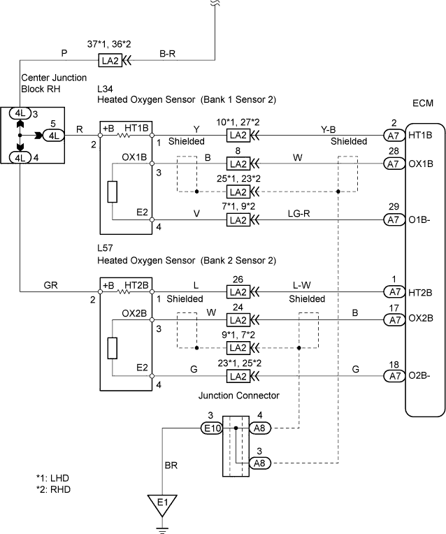
WIRING DIAGRAM
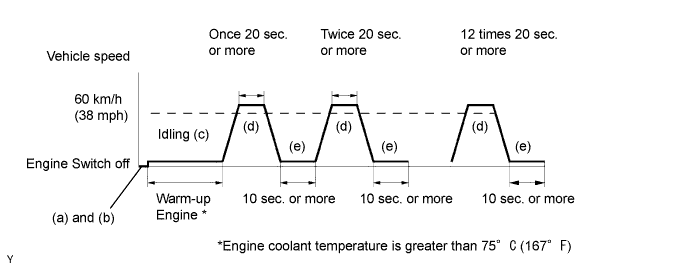
CONFIRMATION DRIVING PATTERN
- (a) Connect the intelligent tester to the DLC3.
- (b) Switch the intelligent tester from normal mode to check mode (Click here).
- (c) Allow the engine to idle until the ECT reaches 75°C (167°F).
- (d) Allow the vehicle to run at 60 km/h (38 mph) or more for 20 seconds or more.
- (e) Allow the engine to idle for 10 seconds or more.
- (f) Perform the 2 previous steps at least 12 times.
- HINT:
- If a malfunction exists, the MIL will be illuminated on the multi-information display.
- NOTICE:
- If the conditions in this test are not strictly followed, detection of a malfunction will not occur. If you do not have the intelligent tester, turn the engine switch off after performing steps "c" to "f", and then perform steps "c" to "f" again.
INSPECTION PROCEDURE
- HINT:
- It is possible that the malfunctioning area can be found using the Active Test Control operation. The Active Test can determine if the heated oxygen sensor or other potential trouble areas are malfunctioning or not.
- The injection volume can be switched to -12.5% (decrease) or +25% (increase) by the Active Test.
- The Active Test procedure enables a technician to check and graph the output voltage of the heated oxygen sensors.
- Procedure:
- Connect the intelligent tester to the DLC3.
- Turn the engine switch on (IG).
- Warm up the engine by running the engine at 2,500 rpm for approximately 90 seconds.
- Enter the following menus: Powertrain / Engine / Active Test / Control the Injection Volume.
- Perform the Active Test while the engine is idling.
- Standard:
- The heated oxygen sensor reacts in accordance with the increase and decrease of injection volume:
+25% → RICH output: More than 0.55 V
-12.5% → LEAN output: Less than 0.4 V
- NOTICE:
- The heated oxygen sensor (sensor 1) output has a few seconds of delay and the heated oxygen sensor (sensor 2) output has a maximum of 20 seconds of delay.
- If the vehicle is short on fuel, the air-fuel ratio becomes LEAN and the DTCs will be recorded.
| Case | Heated Oxygen Sensor Voltage (sensor 1) | Heated Oxygen Sensor Voltage (sensor 2) | Main Suspected Trouble Area | ||
| 1 | Injection Volume +25% -12.5% |  | Injection Volume +25% -12.5% | | - |
| Heated Oxygen Sensor Voltage 0.55 V or more Below 0.4 V |  | Heated Oxygen Sensor Voltage 0.5 V or more Below 0.4 V |  | ||
| 2 | Injection Volume +25% -12.5% | | Injection Volume +25% -12.5% | | Heated oxygen sensor (sensor 1) Heated oxygen sensor heater (sensor 1) |
| Heated Oxygen Sensor Voltage Almost no reaction |  | Heated Oxygen Sensor Voltage 0.5 V or more Below 0.4 V | | ||
| 3 | Injection Volume +25% -12.5% | | Injection Volume +25% -12.5% | | Heated oxygen sensor (sensor 2) Heated oxygen sensor heater (sensor 2) |
| Heated Oxygen Sensor Voltage 0.55 V or more Below 0.4 V | | Heated Oxygen Sensor Voltage Almost no reaction | | ||
| 4 | Injection volume +25% -12.5% | | Injection Volume +25% -12.5% | | Injector fuel pressure, Exhaust gas leak, etc. (air-fuel ratio is extremely LEAN or RICH) |
| Heated Oxygen Sensor Voltage Almost no reaction | | Heated Oxygen Sensor Voltage Almost no reaction | | ||
- HINT:
- Read freeze frame data using the intelligent tester. Freeze frame data records the engine conditions when a malfunction is detected. When troubleshooting, freeze frame data can help determine if the vehicle was running or stopped, if the engine was warmed up or not, if the air-fuel ratio was LEAN or RICH, and other data from the time the malfunction occurred.
- Bank 1 refers to the bank that includes No. 1 cylinder.
- Bank 2 refers to the bank that does not include No. 1 cylinder.
- No. 1 cylinder is located in the front part of the engine, opposite the transmission.
- Sensor 2 refers to the sensor farthest away from the engine body.
| 1.CHECK OTHER DTC OUTPUT (IN ADDITION TO DTC P0136, P0138, P0139, P0156, P0158, P0159) |
Connect the intelligent tester to the DLC3.
Turn the engine switch on (IG) and turn the intelligent tester ON.
Enter the following menus: Powertrain / Engine / DTC.
Read the DTCs.
- Result:
Display (DTC output) Proceed to P0136 or P0156 A P0138, P0139, P0158 or P0159 B P0136, P0138, P0139, P0156, P0158 or P0159 and other DTCs C
- HINT:
- If any other codes besides P0136, P0138, P0139, P0156, P0158 and P0159 are output, perform the troubleshooting for those DTCs first.
|
| ||||
|
| ||||
| A | |
| 2.READ DATA LIST (HEATED OXYGEN SENSOR (SENSOR 2) VOLTAGE) |
Connect the intelligent tester to the DLC3.
Enter the following menus: Powertrain / Engine / Data List / Primary / O2S B1 S2 (or O2S B2 S2).
Allow the engine to run at 2,500 rpm for 3 minutes.
Depress the accelerator pedal quickly until the engine rpm reaches 4,000 rpm 3 times.
- Standard voltage:
- The heated oxygen sensor voltage alternates from below 0.4 V to 0.5 V or more.
|
| ||||
| NG | |
| 3.INSPECT HEATED OXYGEN SENSOR (HEATER RESISTANCE) |
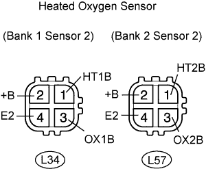 |
Disconnect the L34 and L57 sensor connectors.
Measure the resistance of the sensor.
- Standard resistance:
Tester Connection Specified Condition 1 (HT1B) - 2 (+B) 11 to 16 Ω 1 (HT2B) - 2 (+B) 11 to 16 Ω 1 (HT1B) - 4 (E2) 10 kΩ or higher 1 (HT2B) - 4 (E2) 10 kΩ or higher
|
| ||||
| OK | |
| 4.INSPECT INTEGRATION RELAY (EFI MAIN) |
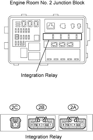 |
Remove the integration relay from the engine room No. 2 junction block.
Measure the resistance of the EFI MAIN relay.
- Standard resistance:
Terminal Connections Specified Condition 2A-8 - 2C-1 10 kΩ or higher 2A-8 - 2C-1 Below 1 Ω
(when battery voltage is applied to terminals 2A-6 and 2A-7)
|
| ||||
| OK | |
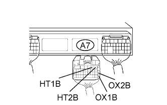
| 5.CHECK WIRE HARNESS (HEATED OXYGEN SENSOR (SENSOR 2) - ECM) |
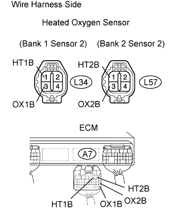 |
Disconnect the L34 and L57 sensor connectors.
Disconnect the A7 ECM connector.
Measure the resistance of the wire harness side connectors.
- Standard resistance:
Tester Connection Specified Condition L34-3 (OX1B) - A7-28 (OX1B) Below 1 Ω L34-1 (HT1B) - A7-2 (HT1B) Below 1 Ω L57-3 (OX2B) - A7-17 (OX2B) Below 1 Ω L57-1 (HT2B) - A7-1 (HT2B) Below 1 Ω L34-3 (OX1B) or A7-28 (OX1B) - Body ground 10 kΩ or higher L34-1 (HT1B) or A7-2 (HT1B) - Body ground 10 kΩ or higher L57-3 (OX2B) or A7-17 (OX2B) - Body ground 10 kΩ or higher L57-1 (HT2B) or A7-1 (HT2B) - Body ground 10 kΩ or higher
|
| ||||
| OK | ||
| ||
| 6.PERFORM CONFIRMATION DRIVING PATTERN |
- HINT:
- Clear all DTCs before performing the confirmation driving pattern.
| NEXT | |
| 7.READ OUTPUT DTC (DTC P0136 OR P0156 IS OUTPUT AGAIN) |
Clear the DTC (Click here).
Start the engine and allow the engine to idle for 15 seconds or more.
Read the DTC.
- Result:
Display (DTC output) Proceed to P0136 or P0156 A No output B
|
| ||||
| A | ||
| ||
| 8.READ DATA LIST (HEATED OXYGEN SENSOR (SENSOR 2) VOLTAGE) |
Connect the intelligent tester to the DLC3.
Enter the following menus: Powertrain / Engine / Data List / Primary / O2S B1 S2 (or O2S B2 S2).
Allow the engine to run at 2,500 rpm for 3 minutes.
Depress the accelerator pedal quickly until the engine rpm reaches 4,000 rpm 3 times.
Result: Heated Oxygen Sensor (sensor 2) Voltage Proceed to More than 1.2 V A Less than 1.0 V B
|
| ||||
| A | |
| 9.CHECK WIRE HARNESS (CHECK FOR SHORT) |
 |
Disconnect the L34 and L57 sensor connectors.
Disconnect the A7 ECM connector.
Measure the resistance of the wire harness side connector.
- Standard resistance:
Tester Connection Specified Condition A7-2 (HT1B) - A7-28 (OX1B) 10 kΩ or higher A7-1 (HT2B) - A7-17 (OX2B) 10 kΩ or higher
|
| ||||
| NG | |
| 10.INSPECT HEATED OXYGEN SENSOR |
|
Disconnect the L34 and L57 sensor connectors.
Measure the resistance of the sensor.
- Standard resistance:
Tester Connection Specified Condition 1 (HT1B) - 2 (+B) 11 to 16 Ω 1 (HT1B) - 2 (+B) 11 to 16 Ω 1 (HT2B) - 4 (E2) 10 kΩ or higher 1 (HT2B) - 4 (E2) 10 kΩ or higher
|
| ||||
| OK | ||
| ||
| 11.READ OUTPUT DTC (DTC P0138, P0139, P0158, OR P0159 IS OUTPUT AGAIN) |
Clear the DTC (Click here).
Start the engine and allow the engine to idle for 15 seconds or more.
Read the DTC.
- Result:
Display (DTC output) Proceed to P0138, P0139, P0158 or P0159 A No output B
|
| ||||
| A | ||
| ||