Engine. Lexus Gs430, Gs300. Uzs190 Grs190
DESCRIPTION
MONITOR DESCRIPTION
WIRING DIAGRAM
INSPECTION PROCEDURE
INSPECT SPARK PLUG
CHECK SPARK AND IGNITION
CHECK WIRE HARNESS (IGNITION COIL - ECM)
CHECK ECM (IGF1, IGF2, VOLTAGE)
CHECK WIRE HARNESS (IGNITION COIL - ECM)
CHECK ECM (IGT1, IGT2, IGT3, IGT4, IGT5, IGT6, IGT7, IGT8 VOLTAGE)
CHECK IGNITION COIL (POWER SOURCE)
CHECK WIRE HARNESS (IGNITION COIL - IG2 RELAY)
DTC P0351 Ignition Coil "A" Primary / Secondary Circuit |
DTC P0352 Ignition Coil "B" Primary / Secondary Circuit |
DTC P0353 Ignition Coil "C" Primary / Secondary Circuit |
DTC P0354 Ignition Coil "D" Primary / Secondary Circuit |
DTC P0355 Ignition Coil "E" Primary / Secondary Circuit |
DTC P0356 Ignition Coil "F" Primary / Secondary Circuit |
DTC P0357 Ignition Coil "G" Primary / Secondary Circuit |
DTC P0358 Ignition Coil "H" Primary / Secondary Circuit |
DESCRIPTION
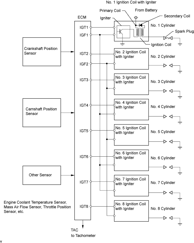
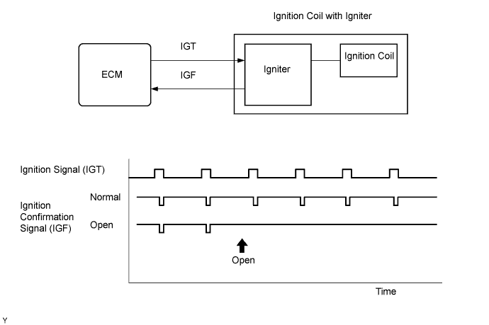
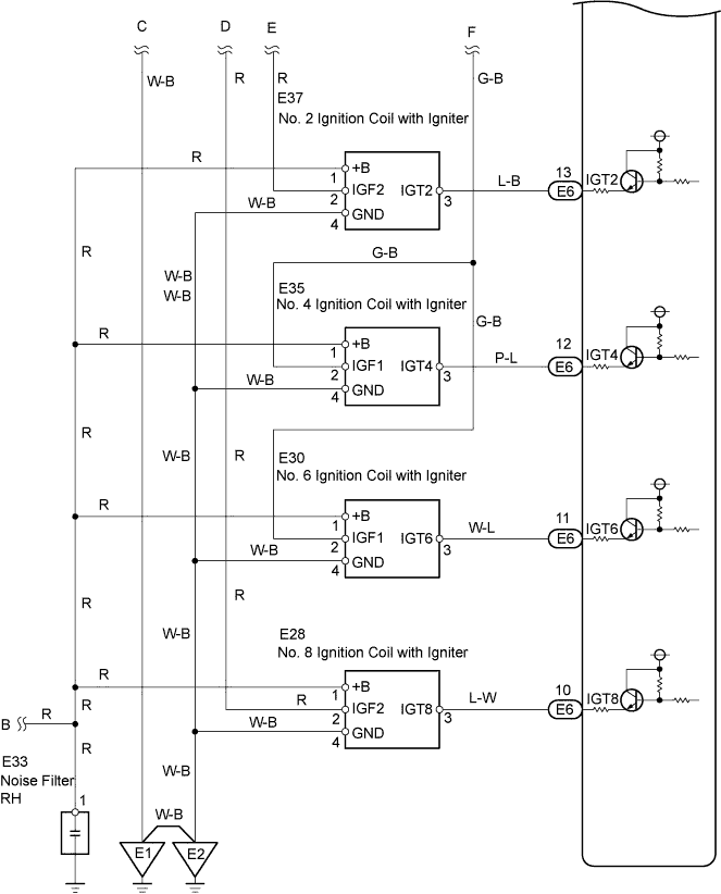
A Direct Ignition System (DIS) is used on this vehicle.The DIS is a 1-cylinder ignition system which ignites one cylinder with one ignition coil. In the 1-cylinder ignition system, the one spark plug is connected to the end of the secondary winding. High voltage generated in the secondary winding is applied directly to the spark plug. The spark of the spark plug passes from the center electrode to the ground electrode.The ECM determines the ignition timing and outputs the ignition signals (IGTs) for each cylinder. Using the IGTs, the ECM turns the power transistor inside the igniter on/off, which switches on/off current to the primary coil. When current to the primary coil is cut off, high voltage is generated in the secondary coil and this voltage is applied to the spark plugs to create sparks inside the cylinders. As the ECM cuts current to the primary coil, the igniter sends back ignition confirmation signals (IGFs) for each cylinder ignition to the ECM.DTC No.
| DTC Detection Condition
| Trouble Area
|
P0351
P0352
P0353
P0354
P0355
P0356
P0357
P0358
| No IGF signal to ECM while engine is running
(1 trip detection logic)
| - Ignition system
- Open or short in IGF or IGT circuit (ignition coil to ECM)
- Ignition coil with igniter (primary coil)
- ECM
|
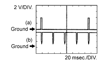
- Reference: Inspection using an oscilloscope.
- While cranking or idling the engine, check the waveform between terminals IGT1 to IGT8 and E1, and IGF1 to IGF2 and E1 of the E6, E8 and E6 ECM connectors.
MONITOR DESCRIPTION
If the ECM does not receive an IGF after sending an IGT, it interprets this as a fault in the igniter and sets a DTC. The monitor runs for 1 second (the first second of engine idle) after the engine is started.
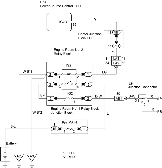
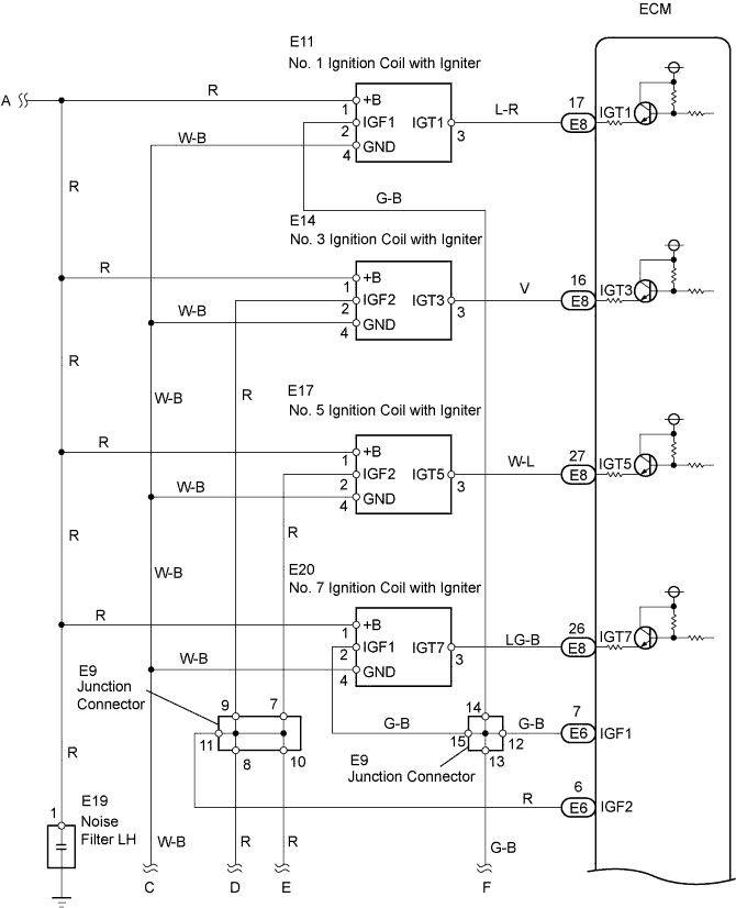
WIRING DIAGRAM
INSPECTION PROCEDURE
- HINT:
- Read freeze frame data using the intelligent tester. Freeze frame data records the engine conditions when a malfunction is detected. When troubleshooting, freeze frame data can help determine if the vehicle was running or stopped, if the engine was warmed up or not, if the air-fuel ratio was LEAN or RICH, and other data from the time the malfunction occurred.
- These DTCs indicate a malfunction related to a primary circuit.
- If DTC P0351 is displayed, check No. 1 ignition coil with igniter circuit.
- If DTC P0352 is displayed, check No. 2 ignition coil with igniter circuit.
- If DTC P0353 is displayed, check No. 3 ignition coil with igniter circuit.
- If DTC P0354 is displayed, check No. 4 ignition coil with igniter circuit.
- If DTC P0355 is displayed, check No. 5 ignition coil with igniter circuit.
- If DTC P0356 is displayed, check No. 6 ignition coil with igniter circuit.
- If DTC P0357 is displayed, check No. 7 ignition coil with igniter circuit.
- If DTC P0358 is displayed, check No. 8 ignition coil with igniter circuit.
Remove the engine cover.
Remove the ignition coil and the spark plug of the misfiring cylinder.
Check the electrode for carbon deposits.
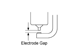
Measure the spark plug's electrode gap.
- Standard:
- Electrode gap: 1.0 to 1.3 mm (0.039 to 0.051 in.)
- Recommended spark plug:
Manufacturer
| Spark Plug Type
|
DENSO
| SK20R11
|
NGK
| IFR6A11
|
- NOTICE:
- If the electrode gap is larger than the standard, replace the spark plug. Do not adjust the electrode gap.
| 2.CHECK SPARK AND IGNITION |
Disconnect the injector connectors to prevent the engine from starting.
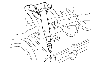
Install the spark plug to the ignition coil.
Attach the spark plug to the cylinder head cover.
Crank the engine within 2 seconds and check the spark.
- OK:
- Spark occurs.
| 3.CHECK WIRE HARNESS (IGNITION COIL - ECM) |
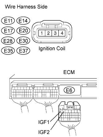
Disconnect the E11, E14, E17, E20, E28, E30, E35 and E37 ignition coil connectors.
Disconnect the E6 ECM connector.
Measure the resistance of the wire harness side connectors.
- Standard resistance:
Tester Connection
| Specified Condition
|
E11-2 (IGF1) - E6-7 (IGF1)
| Below 1 Ω
|
E37-2 (IGF2) - E6-6 (IGF2)
| Below 1 Ω
|
E14-2 (IGF2) - E6-6 (IGF2)
| Below 1 Ω
|
E35-2 (IGF1) - E6-7 (IGF1)
| Below 1 Ω
|
E17-2 (IGF2) - E6-6 (IGF2)
| Below 1 Ω
|
E30-2 (IGF1) - E6-7 (IGF1)
| Below 1 Ω
|
E20-2 (IGF1) - E6-7 (IGF1)
| Below 1 Ω
|
E28-2 (IGF2) - E6-6 (IGF2)
| Below 1 Ω
|
E11-2 (IGF1) or E6-7 (IGF1) - Body ground
| 10 kΩ or higher
|
E37-2 (IGF2) or E6-6 (IGF2) - Body ground
| 10 kΩ or higher
|
E14-2 (IGF2) or E6-6 (IGF2) - Body ground
| 10 kΩ or higher
|
E35-2 (IGF1) or E6-7 (IGF1) - Body ground
| 10 kΩ or higher
|
E17-2 (IGF2) or E6-6 (IGF2) - Body ground
| 10 kΩ or higher
|
E30-2 (IGF1) or E6-7 (IGF1) - Body ground
| 10 kΩ or higher
|
E20-2 (IGF1) or E6-7 (IGF1) - Body ground
| 10 kΩ or higher
|
E28-2 (IGF2) or E6-6 (IGF2) - Body ground
| 10 kΩ or higher
|
| | REPAIR OR REPLACE HARNESS AND CONNECTOR |
|
|
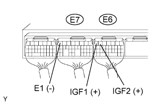
| 4.CHECK ECM (IGF1, IGF2, VOLTAGE) |
Disconnect the E11, E14, E17, E20, E28, E30, E35 and E37 ignition coil connectors.
Turn the engine switch on (IG).
Measure the voltage of the ECM connector.
- Standard voltage:
Tester Connection
| Specified Condition
|
E6-7 (IGF1) - E6-7 (E1)
| 4.5 to 5.5 V
|
E6-6 (IGF2) - E6-7 (E1)
| 4.5 to 5.5 V
|
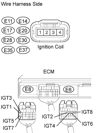
| 5.CHECK WIRE HARNESS (IGNITION COIL - ECM) |
Disconnect the E11, E14, E17, E20, E28, E30, E35 and E37 ignition coil connectors.
Disconnect the E6 and E8 ECM connectors.
Measure the resistance of the wire harness side connectors.
- Standard resistance:
Tester Connection
| Specified Condition
|
E11-3 (IGT1) - E8-17 (IGT1)
| Below 1 Ω
|
E37-3 (IGT2) - E6-13 (IGT2)
| Below 1 Ω
|
E14-3 (IGT3) - E8-16 (IGT3)
| Below 1 Ω
|
E35-3 (IGT4) - E6-12 (IGT4)
| Below 1 Ω
|
E17-3 (IGT5) - E8-27 (IGT5)
| Below 1 Ω
|
E30-3 (IGT6) - E6-11 (IGT6)
| Below 1 Ω
|
E20-3 (IGT7) - E8-26 (IGT7)
| Below 1 Ω
|
E28-3 (IGT8) - E6-10 (IGT8)
| Below 1 Ω
|
E11-3 (IGT1) or E8-17 (IGT1) - Body ground
| 10 kΩ or higher
|
E37-3 (IGT2) or E6-13 (IGT2) - Body ground
| 10 kΩ or higher
|
E14-3 (IGT3) or E8-16 (IGT3) - Body ground
| 10 kΩ or higher
|
E35-3 (IGT4) or E6-12 (IGT4) - Body ground
| 10 kΩ or higher
|
E17-3 (IGT5) or E8-27 (IGT5) - Body ground
| 10 kΩ or higher
|
E30-3 (IGT6) or E6-11 (IGT6) - Body ground
| 10 kΩ or higher
|
E20-3 (IGT7) or E8-26 (IGT7) - Body ground
| 10 kΩ or higher
|
E28-3 (IGT8) or E6-10 (IGT8) - Body ground
| 10 kΩ or higher
|
| | REPAIR OR REPLACE HARNESS AND CONNECTOR |
|
|
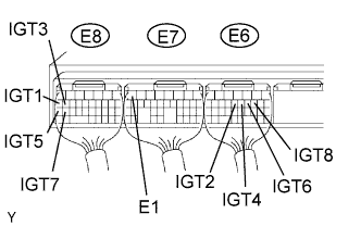
| 6.CHECK ECM (IGT1, IGT2, IGT3, IGT4, IGT5, IGT6, IGT7, IGT8 VOLTAGE) |
Measure the voltage of the ECM connectors when the engine is cranked.
- Standard voltage:
Tester Connection
| Specified Condition
|
E8-17 (IGT1) - E6-7 (E1)
| 0.1 to 4.5 V
|
E6-13 (IGT2) - E6-7 (E1)
| 0.1 to 4.5 V
|
E8-16 (IGT3) - E6-7 (E1)
| 0.1 to 4.5 V
|
E6-12 (IGT4) - E6-7 (E1)
| 0.1 to 4.5 V
|
E8-27 (IGT5) - E6-7 (E1)
| 0.1 to 4.5 V
|
E6-11 (IGT6) - E6-7 (E1)
| 0.1 to 4.5 V
|
E8-26 (IGT7) - E6-7 (E1)
| 0.1 to 4.5 V
|
E6-10 (IGT8) - E6-7 (E1)
| 0.1 to 4.5 V
|
| 7.CHECK IGNITION COIL (POWER SOURCE) |
Disconnect the E11, E14, E17, E20, E28, E30, E35 and E37 ignition coil connectors.
Turn the engine switch from on (IG) to start.
Measure the voltage of the wire harness side connector.
- Standard voltage:
Tester Connection
| Specified Condition
|
E11-1 (+B) - Body ground
| 9 to 14 V
|
E37-1 (+B) - Body ground
| 9 to 14 V
|
E14-1 (+B) - Body ground
| 9 to 14 V
|
E35-1 (+B) - Body ground
| 9 to 14 V
|
E17-1 (+B) - Body ground
| 9 to 14 V
|
E30-1 (+B) - Body ground
| 9 to 14 V
|
E20-1 (+B) - Body ground
| 9 to 14 V
|
E28-1 (+B) - Body ground
| 9 to 14 V
|
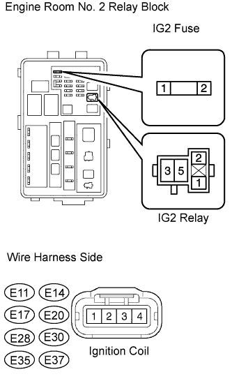
| 8.CHECK WIRE HARNESS (IGNITION COIL - IG2 RELAY) |
Inspect the IG2 fuse.
Remove the IG2 fuse from the engine room No. 2 relay block.
Measure the resistance of the IG2 fuse.
- Standard resistance:
- Below 1 Ω
Disconnect the E11, E14, E17, E20, E28, E30, E35 and E37 ignition coil connectors.
Remove the IG2 relay from the engine room No. 2 relay block.
Measure the resistance of the wire harness side connectors.
- Standard resistance:
Tester Connection
| Specified Condition
|
E11-1 (+B) - Relay block IG2 relay terminal 3
| Below 1 Ω
|
E37-1 (+B) - Relay block IG2 relay terminal 3
| Below 1 Ω
|
E14-1 (+B) - Relay block IG2 relay terminal 3
| Below 1 Ω
|
E35-1 (+B) - Relay block IG2 relay terminal 3
| Below 1 Ω
|
E17-1 (+B) - Relay block IG2 relay terminal 3
| Below 1 Ω
|
E30-1 (+B) - Relay block IG2 relay terminal 3
| Below 1 Ω
|
E20-1 (+B) - Relay block IG2 relay terminal 3
| Below 1 Ω
|
E28-1 (+B) - Relay block IG2 relay terminal 3
| Below 1 Ω
|
E11-1 (+B) or Relay block IG2 relay terminal 3 - Body ground
| 10 kΩ or higher
|
E37-1 (+B) or Relay block IG2 relay terminal 3 - Body ground
| 10 kΩ or higher
|
E14-1 (+B) or Relay block IG2 relay terminal 3 - Body ground
| 10 kΩ or higher
|
E35-1 (+B) or Relay block IG2 relay terminal 3 - Body ground
| 10 kΩ or higher
|
E17-1 (+B) or Relay block IG2 relay terminal 3 - Body ground
| 10 kΩ or higher
|
E30-1 (+B) or Relay block IG2 relay terminal 3 - Body ground
| 10 kΩ or higher
|
E20-1 (+B) or Relay block IG2 relay terminal 3 - Body ground
| 10 kΩ or higher
|
E28-1 (+B) or Relay block IG2 relay terminal 3 - Body ground
| 10 kΩ or higher
|
| | REPAIR OR REPLACE HARNESS AND CONNECTOR |
|
|