Dtc B2414 Steering Position Sensor Malfunction
Lighting. Lexus Gs430, Gs300. Uzs190 Grs190
DESCRIPTION
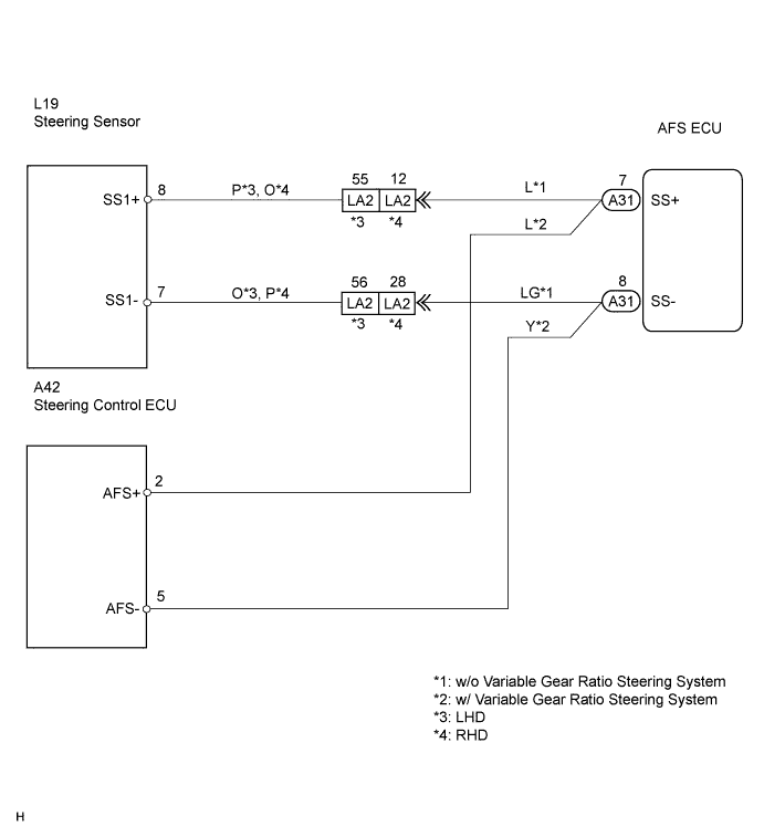
WIRING DIAGRAM
INSPECTION PROCEDURE
READ VALUE OF INTELLIGENT TESTER
CHECK DTC (ABS WITH EBD & BA & TRAC & VSC SYSTEM)
CHECK VEHICLE CONDITION
CHECK WIRE HARNESS (STEERING SENSOR - AFS ECU)
CHECK AFS ECU
CHECK WIRE HARNESS (STEERING CONTROL ECU - AFS ECU)
CHECK AFS ECU
DTC B2414 Steering Position Sensor Malfunction |
DESCRIPTION
The AFS ECU receives signals regarding the swerve-angle from the steering sensor in the steering wheel.DTC No.
| DTC Detection Condition
| Trouble Area
|
B2414
| - Malfunction in steering sensor
- Open or short in steering sensor circuit
| - Steering sensor (w/o Variable gear ratio steering system)
- Steering control ECU (w/ Variable gear ratio steering system)
- Wire harness or connector
- AFS ECU
|
WIRING DIAGRAM
INSPECTION PROCEDURE
| 1.READ VALUE OF INTELLIGENT TESTER |
Connect the intelligent tester to the DLC3.
Turn the engine switch on (IG) and turn the intelligent tester main switch on.
Select the items below in the Data List, and read the displays on the intelligent tester.
- AFS ECU:
Item
| Measurement Item / Display (Range)
| Normal Condition
| Diagnostic Note
|
Steer Sens Sig
| Steering sensor signal value /
-384°to -382.5°
| Approx. 0°
(When steering wheel is straight)
| -
|
- OK:
- Condition sign can be displayed.
ResultOK (When checking from PROBLEM SYMPTOMS TABLE)
| A
|
OK (When checking from DIAGNOSTIC TROUBLE CODE CHART)
| B
|
NG
| C
|
| A |
|
|
|
| PROCEED TO NEXT CIRCUIT INSPECTION SHOWN IN PROBLEM SYMPTOMS TABLE |
|
| 2.CHECK DTC (ABS WITH EBD & BA & TRAC & VSC SYSTEM) |
Check the DTC of ABS with EBD & BA & TRAC & VSC system.
- OK:
- Normal system code is output.
| 3.CHECK VEHICLE CONDITION |
Check vehicle condition.
Resultw/o Variable steering gear ratio control
| A
|
w/ Variable steering gear ratio control
| B
|
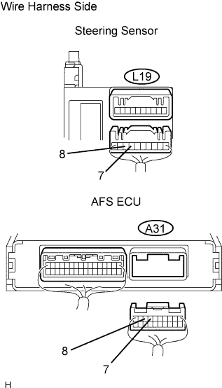
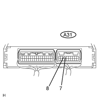
| 4.CHECK WIRE HARNESS (STEERING SENSOR - AFS ECU) |
Disconnect the L19 steering sensor connector .
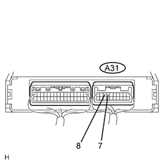
Disconnect the A31 AFS ECU connector.
Measure the resistance of the wire harness side connectors.
- Standard resistance:
Tester Connection
| Condition
| Specified Condition
|
L19-7 (SS1-) - A31-8 (SS-)
| Always
| Below 1 Ω
|
L19-8 (SS1+) - A31-7 (SS+)
| Always
| Below 1 Ω
|
A31-8 (SS1-) - Body ground
| Always
| 10 kΩ or higher
|
A31-7 (SS1+) - Body ground
| Always
| 10 kΩ or higher
|
| | REPAIR OR REPLACE HARNESS AND CONNECTOR |
|
|
Reconnect the L19 steering sensor connector.
Reconnect the A31 AFS ECU connector.
Measure the voltage of the connector.
- Standard voltage:
Tester Connection
| Condition
| Specified Condition
|
A31-7 (SS+) - A31-8 (SS-)
| Engine switch on (IG)
| 0 to 5 V
(Pulse generation)
|
ResultOK (When checking from DIAGNOSTIC TROUBLE CODE CHART)
| A
|
OK (When checking from PROBLEM SYMPTOMS TABLE)
| B
|
NG
| C
|
| | PROCEED TO NEXT CIRCUIT INSPECTION SHOWN IN PROBLEM SYMPTOMS TABLE |
|
|
| |
|
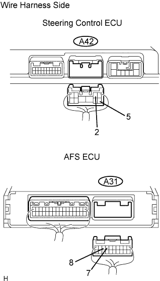
| 6.CHECK WIRE HARNESS (STEERING CONTROL ECU - AFS ECU) |
Disconnect the A42 steering control ECU connector.
Disconnect the A31 AFS ECU connector.
Measure the resistance of the wire harness side connectors.
- Standard resistance:
Tester Connection
| Condition
| Specified Condition
|
A42-5 (AFS-) - A31-8 (SS-)
| Always
| Below 1 Ω
|
A42-2 (AFS+) - A31-7 (SS+)
| Always
| Below 1 Ω
|
A31-8 (SS1-) - Body ground
| Always
| 10 kΩ or higher
|
A31-7 (SS1+) - Body ground
| Always
| 10 kΩ or higher
|
| | REPAIR OR REPLACE HARNESS AND CONNECTOR |
|
|
Reconnect the A31 AFS ECU connector.
Measure the voltage of the connector.
- Standard voltage:
Tester Connection
| Condition
| Specified Condition
|
A31-7 (SS+) - A31-8 (SS-)
| Engine switch on (IG)
| 0 to 5 V
(Pulse generation)
|
ResultOK (When checking from DIAGNOSTIC TROUBLE CODE CHART)
| A
|
OK (When checking from PROBLEM SYMPTOMS TABLE)
| B
|
NG
| C
|
| | PROCEED TO NEXT CIRCUIT INSPECTION SHOWN IN PROBLEM SYMPTOMS TABLE |
|
|
| | REPLACE STEERING CONTROL ECU |
|
|