Dtc B1462/62 Room Humidity Sensor Circuit
DESCRIPTION
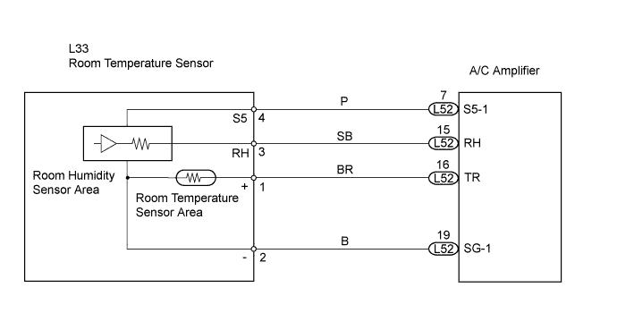
WIRING DIAGRAM
INSPECTION PROCEDURE
READ VALUE OF INTELLIGENT TESTER
CHECK WIRE HARNESS (ROOM TEMPERATURE SENSOR - A/C AMPLIFIER)
CHECK AIR CONDITIONING AMPLIFIER
CHECK ROOM HUMIDITY SENSOR
DTC B1462/62 Room Humidity Sensor Circuit |
DESCRIPTION
The room humidity sensor detects room humidity. The voltage of the room humidity sensor changes in accordance with room humidity. The A/C amplifier reads changes in the room humidity sensor.The room humidity sensor is integrated with the room temperature sensor.DTC No.
| DTC Detection Condition
| Trouble Area
|
B1462/62
| Open or short in room humidity sensor circuit
| - Room humidity sensor (room temperature sensor)
- Harness and connector between room humidity sensor (room temperature sensor) and A/C amplifier
- A/C amplifier
|
WIRING DIAGRAM
INSPECTION PROCEDURE
| 1.READ VALUE OF INTELLIGENT TESTER |
Connect the intelligent tester to the DLC3.
Turn the engine switch on (IG) and push the intelligent tester main switch on.
Select the item below in the Data List, and read the display on the intelligent tester.
A/C amplifier:Item
| Measurement Item / Display
(Range)
| Normal Condition
| Diagnostic Note
|
Humidity Sensor
(Humidity Sens)
| Humidity Sensor /
Min.: 0%, Max.: 100%
| Actual room humidity is displayed
| -
|
- OK:
- The display is as specified in the normal condition.
Result:NG
| A
|
OK (Checking from the PROBLEM SYMPTOMS TABLE)
| B
|
OK (Checking from the DTC)
| C
|
| | PROCEED TO NEXT CIRCUIT INSPECTION SHOWN IN PROBLEM SYMPTOMS TABLE |
|
|
| | REPLACE AIR CONDITIONING AMPLIFIER |
|
|
| 2.CHECK WIRE HARNESS (ROOM TEMPERATURE SENSOR - A/C AMPLIFIER) |
Disconnect the L33 room temperature sensor connector.
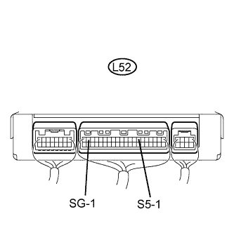
Disconnect the L52 A/C amplifier connector.
Measure the resistance of the wire harness side connectors.
- Standard resistance:
Tester Connection
| Condition
| Specified Condition
|
L33-3 (RH) - L52-15 (RH)
| Always
| Below 1 Ω
|
L33-4 (S5) - L52-7 (S5-1)
| Always
| Below 1 Ω
|
L33-2 (-) - L52-19 (SG-1)
| Always
| Below 1 Ω
|
L52-19 (SG-1) - Body ground
| Always
| 10 kΩ or higher
|
L52-15 (RH) - Body ground
| Always
| Below 1 Ω
|
L52-7 (S5-1) - Body ground
| Always
| 10 kΩ or higher
|
| | REPAIR OR REPLACE HARNESS AND CONNECTOR |
|
|
| 3.CHECK AIR CONDITIONING AMPLIFIER |
Remove the A/C amplifier with its connectors still connected.
Measure the voltage of the connector.
- Standard voltage:
Tester Connection
| Condition
| Specified Condition
|
L52-7 (S5-1) - L52-19 (SG-1)
| Engine switch on (IG)
| 4.5 to 5.5 V
|
| | REPLACE AIR CONDITIONING AMPLIFIER |
|
|
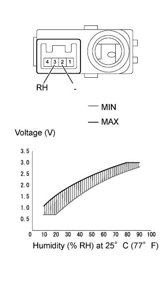
| 4.CHECK ROOM HUMIDITY SENSOR |
Remove the room temperature sensor.
Measure the voltage of the sensor.
- Standard voltage:
Tester Connection
| Condition
| Specified Condition
|
2 (-) - 3 (RH)
| 10%
| 0.70 to 1.08 V
|
2 (-) - 3 (RH)
| 20%
| 0.72 to 1.57 V
|
2 (-) - 3 (RH)
| 30%
| 1.13 to 1.95 V
|
2 (-) - 3 (RH)
| 40%
| 1.61 to 2.24 V
|
2 (-) - 3 (RH)
| 50%
| 1.99 to 2.46 V
|
2 (-) - 3 (RH)
| 60%
| 2.26 to 2.66 V
|
2 (-) - 3 (RH)
| 70%
| 2.48 to 2.85 V
|
2 (-) - 3 (RH)
| 80%
| 2.68 to 3.04 V
|
2 (-) - 3 (RH)
| 90%
| 2.87 to 3.05 V
|
- NOTICE:
- Do not touch the humidity sensor as body heat will affect the inspection results. When performing the inspection, hold the sensor by its connector.
- Allow the sensor to acclimate to the ambient temperature and humidity before performing the inspection.
- The standard voltages in the table above are based on inspections performed when the ambient temperature is 25°C (77°F).
- HINT:
- As the humidity increases, the resistance decreases (see the graph).
| | REPLACE ROOM HUMIDITY SENSOR |
|
|
| OK |
|
|
|
| REPLACE AIR CONDITIONING AMPLIFIER |
|