Heater & Air Conditioning System. Lexus Gs430, Gs300. Uzs190 Grs190
Air Conditioning. Lexus Gs430, Gs300. Uzs190 Grs190
READ VALUE OF INTELLIGENT TESTER
INSPECT AMBIENT TEMPERATURE SENSOR
CHECK WIRE HARNESS (AMBIENT TEMPERATURE SENSOR - ECM)
DTC B1412/12 Ambient Temperature Sensor Circuit |
DESCRIPTION
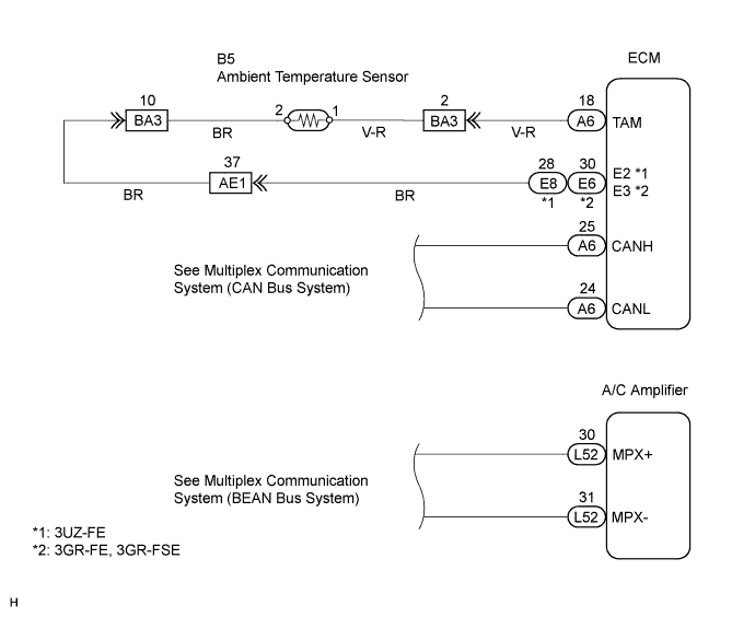
The ambient temperature sensor is installed in the front part of the condenser to detect the ambient temperature and control the air conditioner "AUTO" mode. The sensor connected to the ECM detects fluctuations in the ambient temperature. This data is used for controlling the room temperature. The sensor sends a signal to the A/C amplifier via the ECM. The resistance of the ambient temperature sensor changes in accordance with the ambient temperature. As the temperature decreases, the resistance increases. As the temperature increases, the resistance decreases.The ECM applies voltage (5 V) to the ambient temperature sensor and reads voltage changes as the resistance of the ambient temperature sensor changes. The ECM sends the read signal to the A/C amplifier via CAN and body multiplex communications.
| DTC No. | DTC Detection Condition | Trouble Area |
| B1412/12 | Open or short in ambient temperature sensor circuit |
|
WIRING DIAGRAM
INSPECTION PROCEDURE
| 1.READ VALUE OF INTELLIGENT TESTER |
Connect the intelligent tester to the DLC3.
Turn the engine switch on (IG) and push the intelligent tester main switch on.
Select the item below in the Data List, and read the display on the intelligent tester.
| Item | Measurement Item / Display (Range) | Normal Condition | Diagnostic Note |
| Ambient Temp Sensor (Ambi Temp Sens) | Ambient temperature sensor / Min: -23.3°C (-9.94°F) Max: 65.95°C (150.71°F) | Actual ambient temperature is displayed | Open in circuit: -23.3°C (-9.94°F) Short in the circuit: 65.95°C (150.71°F) |
- OK:
- The display is as specified in the normal condition.
| NG | A |
| OK (Checking from the PROBLEM SYMPTOMS TABLE) | B |
| OK (Checking from the DTC) | C |
|
| ||||
|
| ||||
| A | |
| 2.INSPECT AMBIENT TEMPERATURE SENSOR |
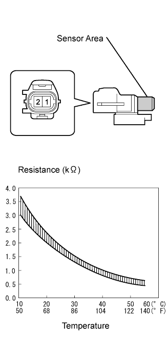 |
Remove the ambient temperature sensor.
Measure the resistance of the sensor.
- Standard resistance:
Tester Connection Condition Specified Condition 1 - 2 10°C (50°F) 3.00 to 3.73 kΩ 1 - 2 15°C (59°F) 2.45 to 2.88 kΩ 1 - 2 20°C (68°F) 1.95 to 2.30 kΩ 1 - 2 25°C (77°F) 1.60 to 1.80 kΩ 1 - 2 30°C (86°F) 1.28 to 1.47 kΩ 1 - 2 35°C (95°F) 1.00 to 1.22 kΩ 1 - 2 40°C (104°F) 0.80 to 1.00 kΩ 1 - 2 45°C (113°F) 0.65 to 0.85 kΩ 1 - 2 50°C (122°F) 0.50 to 0.70 kΩ 1 - 2 55°C (131°F) 0.44 to 0.60 kΩ 1 - 2 60°C (140°F) 0.36 to 0.50 kΩ
- NOTICE:
- Even slightly touching the sensor may change the resistance value. Be sure to hold the connector of the sensor.
- When measuring, the sensor temperature must be the same as the ambient temperature.
- HINT:
- As the temperature increases, the resistance decreases (see the graph).
|
| ||||
| OK | |
| 3.CHECK WIRE HARNESS (AMBIENT TEMPERATURE SENSOR - ECM) |
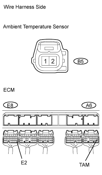 |
3UZ-FE
Disconnect the B5 ambient temperature sensor connector.
Disconnect the A6 and E8 ECM connectors .
Measure the resistance of the wire harness side connectors.
- Standard resistance:
Tester Connection Condition Specified Condition B5-1 - A6-18 (TAM) Always Below 1 Ω B5-2 - E8-28 (E2) Always Below 1 Ω A6-18 (TAM) - Body ground Always 10 kΩ or higher E8-28 (E2) - Body ground Always 10 kΩ or higher
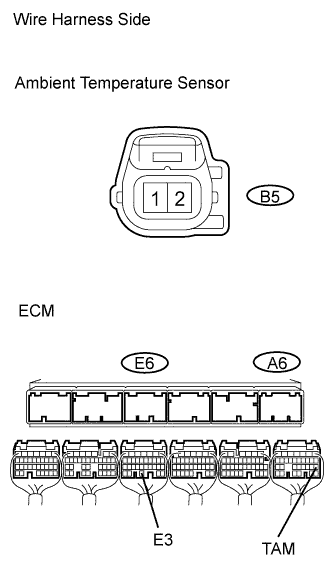
3GR-FE, 3GR-FSE
Disconnect the B5 ambient temperature sensor connector.
Disconnect the A6 and E6 ECM connectors.
Measure the resistance of the wire harness side connectors.
- Standard resistance:
Tester Connection Condition Specified Condition B5-1 - A6-18 (TAM) Always Below 1 Ω B5-2 - E6-30 (E3) Always Below 1 Ω A6-18 (TAM) - Body ground Always 10 kΩ or higher E6-30 (E3) - Body ground Always 10 kΩ or higher
 |
|
| ||||
| OK | ||
| ||