Rear Shock Absorber Installation
INSTALL REAR SHOCK ABSORBER WITH COIL SPRING
INSTALL ABSORBER CONTROL ACTUATOR (for AVS)
INSTALL REAR SHOCK ABSORBER CAP
TEMPORARILY TIGHTEN REAR SUSPENSION NO.2 ARM
STABILIZE SUSPENSION
FULLY TIGHTEN REAR SUSPENSION NO. 2 ARM
INSTALL REAR SUSPENSION MEMBER BRACE
INSTALL DIFFERENTIAL NO.2 SUPPORT PROTECTOR
INSTALL REAR TIRE
INSTALL LUGGAGE COMPARTMENT TRIM COVER INNER
INSTALL REAR FLOOR FINISH PLATE
INSTALL TOOL BOX
INSTALL TOOL BOX BOARD
INSTALL LUGGAGE COMPARTMENT TRIM SIDE COVER LH
INSTALL LUGGAGE COMPARTMENT TRIM SIDE COVER RH
INSTALL LUGGAGE COMPARTMENT FLOOR MAT
CONNECT CABLE TO NEGATIVE BATTERY TERMINAL
INSPECT ADAPTIVE VARIABLE SUSPENSION SYSTEM
PERFORM INITIALIZATION
INSPECT AND ADJUST REAR WHEEL ALIGNMENT
Rear Shock Absorber -- Installation |
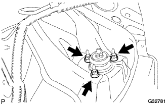
| 1. INSTALL REAR SHOCK ABSORBER WITH COIL SPRING |
Temporarily install the rear shock absorber with rear coil spring with the 2 bolts.
Install the 3 nuts on the upper side of the rear shock absorber with coil spring.
- Torque:
- 74 N*m{755 kgf*cm, 55 ft.*lbf}
Tighten the lock nut.
- Torque:
- 18 N*m{184 kgf*cm, 13 ft.*lbf}
Tighten the 2 bolts.
- Torque:
- 21 N*m{214 kgf*cm, 16 ft.*lbf}
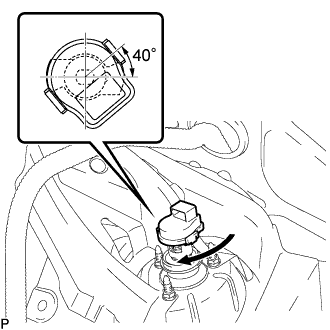
| 2. INSTALL ABSORBER CONTROL ACTUATOR (for AVS) |
Check that the control rod of the rear shock absorber is in the position shown in the illustration.
- NOTICE:
- If the control rod is not in the position shown in the illustration, turn the control rod to adjust the position and install the absorber control actuator.
Install the absorber control actuator to the actuator support bracket. Turn the actuator clockwise approximately 40°until a click is felt.
- NOTICE:
- Do not excessively turn the actuator.
| 3. INSTALL REAR SHOCK ABSORBER CAP |
Connect the connector and install the shock absorber cap.
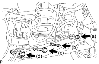
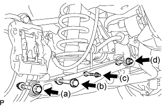
| 4. TEMPORARILY TIGHTEN REAR SUSPENSION NO.2 ARM |
Temporarily install the rear suspension No.2 arm with the bolt, nut and washer.
Temporarily install the rear suspension No.2 arm with the bolt and nut.
Temporarily install the rear shock absorber with coil spring with the bolt and nut.
Temporarily install the stabilizer link assembly and the load sensing valve sensor bracket to the rear suspension No.2 arm with the bolt and nut.
Install the front wheel.
- Torque:
- 103 N*m{1,050 kgf*cm, 76 ft.*lbf}
Lower the vehicle and bounce it up and down several times to stabilize the front suspension.
Remove the front wheel.
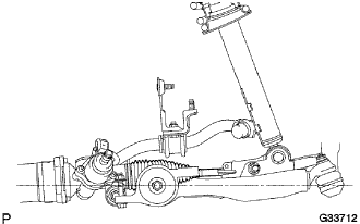
Jack up the front suspension lower arm placing a wooden block in between. Apply a load to the front suspension so that the front suspension lower arm is placed in a horizontal position.
| 6. FULLY TIGHTEN REAR SUSPENSION NO. 2 ARM |
Fully tighten the bolt on the axle carrier side.
- Torque:
- 161 N*m{1,640 kgf*cm, 119 ft.*lbf}
- NOTICE:
- Turn the bolt while holding the nut.
Fully tighten the bolt holding the rear shock absorber with coil spring.
- Torque:
- 110 N*m{1,120 kgf*cm, 81 ft.*lbf}
- NOTICE:
- Turn the bolt while holding the nut.
Fully tighten the nut holding the rear stabilizer link assembly.
- Torque:
- 27 N*m{275 kgf*cm, 20 ft.*lbf}
Fully tighten the nut on the rear suspension member side.
- Torque:
- 140 N*m{1,430 kgf*cm, 103 ft.*lbf}
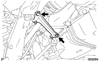
| 7. INSTALL REAR SUSPENSION MEMBER BRACE |
Install the rear suspension member brace with the 2 bolts.
- Torque:
- 50 N*m{510 kgf*cm, 37 ft.*lbf}
| 8. INSTALL DIFFERENTIAL NO.2 SUPPORT PROTECTOR |
Install the differential No.2 support protector with the 2 nuts.
- Torque:
- 103 N*m{1,050 kgf*cm, 76 ft.*lbf}
| 10. INSTALL LUGGAGE COMPARTMENT TRIM COVER INNER |
| 11. INSTALL REAR FLOOR FINISH PLATE |
| 13. INSTALL TOOL BOX BOARD |
| 14. INSTALL LUGGAGE COMPARTMENT TRIM SIDE COVER LH |
| 15. INSTALL LUGGAGE COMPARTMENT TRIM SIDE COVER RH |
| 16. INSTALL LUGGAGE COMPARTMENT FLOOR MAT |
| 17. CONNECT CABLE TO NEGATIVE BATTERY TERMINAL |
| 18. INSPECT ADAPTIVE VARIABLE SUSPENSION SYSTEM |
(Click here)
| 19. PERFORM INITIALIZATION |
| 20. INSPECT AND ADJUST REAR WHEEL ALIGNMENT |
(Click here)