Valve Clearance -- Adjustment |
| 1. REMOVE V-BANK COVER |
Remove the 2 nuts and V-bank cover.
| 2. REMOVE CYLINDER HEAD COVER SUB-ASSEMBLY RH |
Remove the bolt, and disconnect the wire clamp bracket from the camshaft bearing cap.
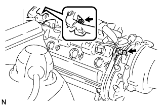 |
Remove the bolt, and disconnect the engine wire protector from the cylinder head cover.
Remove the 9 bolts, 9 seal washers and cylinder head cover.
| 3. REMOVE CYLINDER HEAD COVER SUB-ASSEMBLY LH |
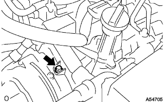
Remove the bolt, and disconnect the wire clamp bracket from the camshaft bearing cap.
 |
Remove the 9 bolts, 9 seal washers and cylinder head cover.
| 4. SET NO. 1 CYLINDER TO TDC/COMPRESSION |
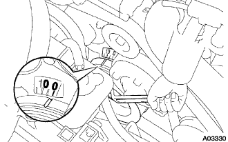
Turn the crankshaft damper, and align its groove with timing mark "0" of the timing belt No. 1 cover.
 |
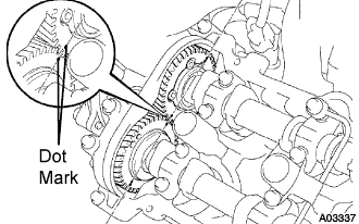
Check that the timing marks (1 dot mark each) of the intake and exhaust camshaft gears (on the LH bank) are aligned.
If not, turn the crankshaft 1 revolution (360°) and align the timing marks.
 |
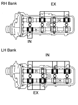
| 5. INSPECT VALVE CLEARANCE |
Check only the valves indicated.
Using a feeler gauge, measure the clearance between the valve lifter and camshaft.
- Valve clearance (Cold):
Valve Specified Condition Intake 0.15 to 0.25 mm (0.006 to 0.010 in.) Exhaust 0.25 to 0.35 mm (0.010 to 0.014 in.)
Record valve clearance measurements that are out of the specified range. These measurements will be used later to determine the size of the adjustment shim to be installed.
 |
Turn the crankshaft 1 revolution (360°) and align the mark.
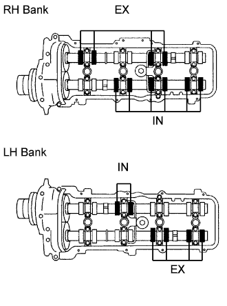 |
Check only the valves indicated in the illustration. Measure the valve clearance.
- Valve clearance (Cold):
Valve Specified Condition Intake 0.15 to 0.25 mm (0.006 to 0.010 in.) Exhaust 0.25 to 0.35 mm (0.010 to 0.014 in.)
| 6. REMOVE CAMSHAFT |
Remove the camshaft (Click here).
| 7. REMOVE NO. 3 CAMSHAFT SUB-ASSEMBLY |
Remove the camshaft (Click here).
| 8. ADJUST VALVE CLEARANCE |
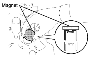
Using a powerful magnet, remove the valve lifter and adjusting shim.
- NOTICE:
- Since shims might drop inside the cylinder head, the operation should be performed slowly.
- Shims should be classified by the installation.
 |
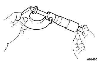
Determine the replacement adjusting shim size according to these formulas and charts.
Using a micrometer, measure the thickness of the removed shim.
Calculate the thickness of a new shim so that a valve clearance is within the specified value.
T = Thickness of removed shim
A = Measured valve clearance- Valve clearance:
Valve Standard Thickness Intake T + (A 0.20 mm (0.008 in.)) Exhaust T + (A 0.30 mm (0.012 in.))
 |
Select a new shim with a thickness as close as possible to the calculated value.
- HINT:
- Shims are available in 41 increments of 0.020 mm (0.0008 in.), from 2.00 mm (0.0787 in.) to 2.80 mm (0.1102).
Install a new adjusting shim to the spring retainer.
Install the valve lifter.
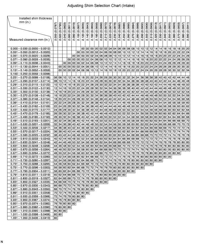
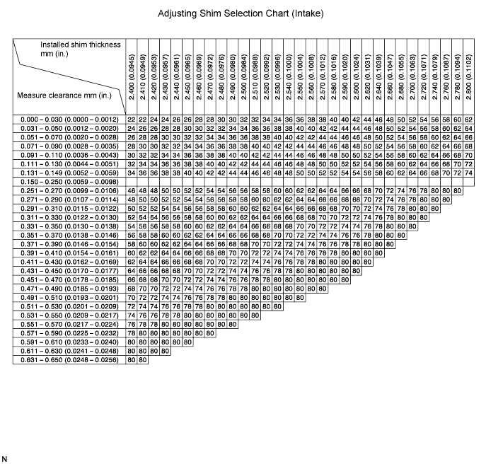
- Intake valve clearance (Cold):
- 0.15 to 0.25 mm (0.006 to 0.010 in.)
EXAMPLE:
The 2.300 mm (0.0906 in.) shim is installed, and the measured clearance is 0.440 mm (0.0173 in.). Replace the 2.300 mm (0.0906 in.) shim with a No. 54 shim.
- New Shim Thickness:
Shim No. Thickness Shim No. Thickness Shim No. Thickness 00 2.000 mm (0.0787 in.) 28 2.280 mm (0.0898 in.) 56 2.560 mm (0.1008 in.) 02 2.020 mm (0.0795 in.) 30 2.300 mm (0.0906 in.) 58 2.580 mm (0.1016 in.) 04 2.040 mm (0.0803 in.) 32 2.320 mm (0.0913 in.) 60 2.600 mm (0.1024 in.) 06 2.060 mm (0.0811 in.) 34 2.340 mm (0.0921 in.) 62 2.620 mm (0.1031 in.) 08 2.080 mm (0.0819 in.) 36 2.360 mm (0.0929 in.) 64 2.640 mm (0.1039 in.) 10 2.100 mm (0.0827 in.) 38 2.380 mm (0.0937 in.) 66 2.660 mm (0.1047 in.) 12 2.120 mm (0.0835 in.) 40 2.400 mm (0.0945 in.) 68 2.680 mm (0.1055 in.) 14 2.140 mm (0.0843 in.) 42 2.420 mm (0.0953 in.) 70 2.700 mm (0.1063 in.) 16 2.160 mm (0.0850 in.) 44 2.440 mm (0.0961 in.) 72 2.720 mm (0.1071 in.) 18 2.180 mm (0.0858 in.) 46 2.460 mm (0.0969 in.) 74 2.740 mm (0.1079 in.) 20 2.200 mm (0.0866 in.) 48 2.480 mm (0.0976 in.) 76 2.760 mm (0.1087 in.) 22 2.220 mm (0.0874 in.) 50 2.500 mm (0.0984 in.) 78 2.780 mm (0.1094 in.) 24 2.240 mm (0.0882 in.) 52 2.520 mm (0.0992 in.) 80 2.800 mm (0.1102 in.) 26 2.260 mm (0.0890 in.) 54 2.540 mm (0.1000) in.
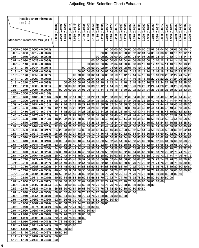
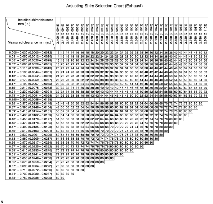
- Exhaust valve clearance (Cold):
- 0.25 to 0.35 mm (0.010 to 0.014 in.)
EXAMPLE:
The 2.300 mm (0.0906 in.) shim is installed, and the measured clearance is 0.440 mm (0.0173 in.). Replace the 2.300 mm (0.0906 in.) shim with a No. 44 shim.
- New Shim Thickness:
Shim No. Thickness Shim No. Thickness Shim No. Thickness 00 2.000 mm (0.0787 in.) 28 2.280 mm (0.0898 in.) 56 2.560 mm (0.1008 in.) 02 2.020 mm (0.0795 in.) 30 2.300 mm (0.0906 in.) 58 2.580 mm (0.1016 in.) 04 2.040 mm (0.0803 in.) 32 2.320 mm (0.0913 in.) 60 2.600 mm (0.1024 in.) 06 2.060 mm (0.0811 in.) 34 2.340 mm (0.0921 in.) 62 2.620 mm (0.1031 in.) 08 2.080 mm (0.0819 in.) 36 2.360 mm (0.0929 in.) 64 2.640 mm (0.1039 in.) 10 2.100 mm (0.0827 in.) 38 2.380 mm (0.0937 in.) 66 2.660 mm (0.1047 in.) 12 2.120 mm (0.0835 in.) 40 2.400 mm (0.0945 in.) 68 2.680 mm (0.1055 in.) 14 2.140 mm (0.0843 in.) 42 2.420 mm (0.0953 in.) 70 2.700 mm (0.1063 in.) 16 2.160 mm (0.0850 in.) 44 2.440 mm (0.0961 in.) 72 2.720 mm (0.1071 in.) 18 2.180 mm (0.0858 in.) 46 2.460 mm (0.0969 in.) 74 2.740 mm (0.1079 in.) 20 2.200 mm (0.0866 in.) 48 2.480 mm (0.0976 in.) 76 2.760 mm (0.1087 in.) 22 2.220 mm (0.0874 in.) 50 2.500 mm (0.0984 in.) 78 2.780 mm (0.1094 in.) 24 2.240 mm (0.0882 in.) 52 2.520 mm (0.0992 in.) 80 2.800 mm (0.1102 in.) 26 2.260 mm (0.0890 in.) 54 2.540 mm (0.1000) in.
| 9. INSTALL NO. 3 CAMSHAFT SUB-ASSEMBLY |
Install the camshaft (Click here).
| 10. INSTALL CAMSHAFT |
Install the camshaft (Click here).
| 11. INSTALL CYLINDER HEAD COVER SUB-ASSEMBLY LH |
Remove any old packing (FIPG) material.
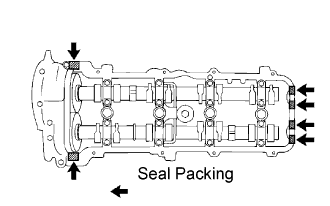 |
Apply seal packing to the cylinder heads as shown in the illustration.
- Seal packing:
- Part No. 08826-00080 or equivalent
- NOTICE:
- Remove any oil from the contact surface.
- Install the oil pan within 5 minutes after applying seal packing.
- Do not start the engine within 2 hours after applying seal packing.
Install the gasket to the cylinder head cover.
Install the seal washer to the bolt.
Install the cylinder head cover with the 9 bolts. Uniformly tighten the bolts in several passes.
- Torque:
- 6.0 N*m{61 kgf*cm, 53 in.*lbf}
Install the wire clamp bracket on the engine wire to the cylinder head.
Install the wire clamp bracket on the engine wire to the camshaft bearing cap.
| 12. INSTALL CYLINDER HEAD COVER SUB-ASSEMBLY RH |
Remove any old packing (FIPG) material.
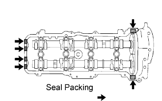 |
Apply seal packing to the cylinder heads as shown in the illustration.
- Seal packing:
- Part No. 08826-00080 or equivalent
- NOTICE:
- Remove any oil from the contact surface.
- Install the oil pan within 5 minutes after applying seal packing.
- Do not start the engine within 2 hours after applying seal packing.
Install the gasket to the cylinder head cover.
Install the seal washer to the bolt.
Install the cylinder head cover with the 9 bolts. Uniformly tighten the bolts in several passes.
- Torque:
- 6.0 N*m{61 kgf*cm, 53 in.*lbf}
Install the wire clamp bracket on the engine wire to the cylinder head.
Install the wire clamp bracket on the engine wire to the camshaft bearing cap.