Rear View Monitor System Display Signal Circuit Between Television Camera Ecu And Multi-Display
DESCRIPTION
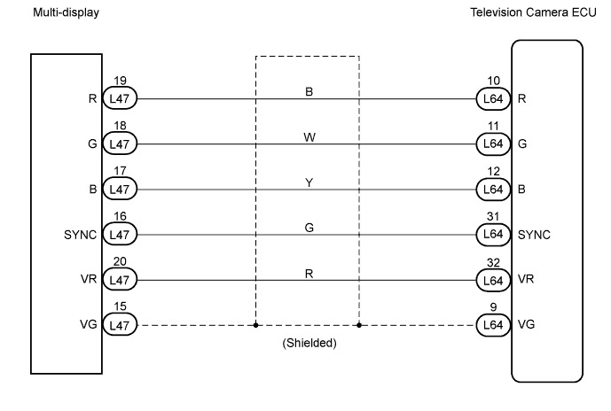
WIRING DIAGRAM
INSPECTION PROCEDURE
CHECK WIRE HARNESS (TELEVISION CAMERA ECU - MULTI-DISPLAY)
REAR VIEW MONITOR SYSTEM - Display Signal Circuit between Television Camera ECU and Multi-display |
DESCRIPTION
This is the display signal circuit from the television camera ECU to the multi-display.
WIRING DIAGRAM
INSPECTION PROCEDURE
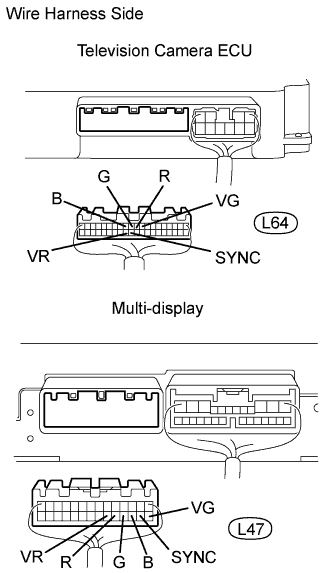
| 1.CHECK WIRE HARNESS (TELEVISION CAMERA ECU - MULTI-DISPLAY) |
Disconnect the L64 ECU connector.
Disconnect the L47 multi-display connector.
Measure the resistance of the wire harness side connectors.
- Standard resistance:
Tester Connection
| Condition
| Specified Condition
|
L64-10 (R) - L47-19 (R)
| Always
| Below 1 Ω
|
L64-11 (G) - L47-18 (G)
| Always
| Below 1 Ω
|
L64-12 (B) - L47-17 (B)
| Always
| Below 1 Ω
|
L64-31 (SYNC) - L47-16 (SYNC)
| Always
| Below 1 Ω
|
L64-32 (VR) - L47-20 (VR)
| Always
| Below 1 Ω
|
L64-9 (VG) - L47-15 (VG)
| Always
| Below 1 Ω
|
L64-10 (R) - Body ground
| Always
| 10 kΩ or higher
|
L64-11 (G) - Body ground
| Always
| 10 kΩ or higher
|
L64-12 (B) - Body ground
| Always
| 10 kΩ or higher
|
L64-31 (SYNC) - Body ground
| Always
| 10 kΩ or higher
|
L64-32 (VR) - Body ground
| Always
| 10 kΩ or higher
|
L64-9 (VG) - Body ground
| Always
| 10 kΩ or higher
|
| | REPAIR OR REPLACE HARNESS AND CONNECTOR |
|
|
| OK |
|
|
|
| PROCEED TO NEXT CIRCUIT INSPECTION SHOWN IN PROBLEM SYMPTOMS TABLE |
|