Rear View Monitor System Display Signal Circuit (Television Camera Assembly - Television Camera Ecu)
DESCRIPTION
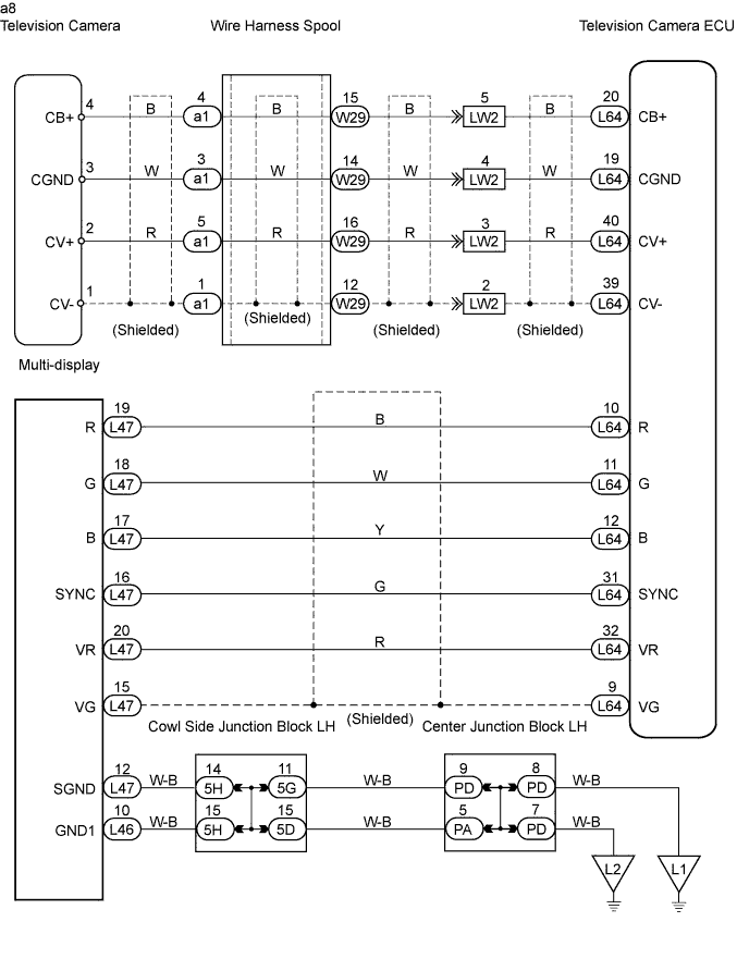
WIRING DIAGRAM
INSPECTION PROCEDURE
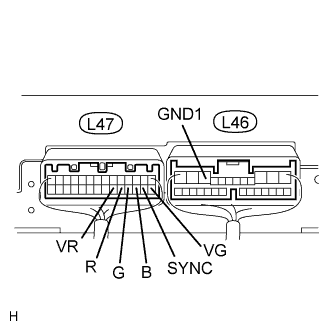
INSPECT MULTI-DISPLAY (R, G, B, VR, VG, SYNC TERMINAL)
CHECK WIRE HARNESS (TELEVISION CAMERA ECU - TELEVISION CAMERA)
CHECK TELEVISION CAMERA (POWER SOURCE VOLTAGE)
REAR VIEW MONITOR SYSTEM - Display Signal Circuit (Television Camera Assembly - Television Camera ECU) |
DESCRIPTION
This is the display signal circuit of the television camera.
WIRING DIAGRAM
INSPECTION PROCEDURE
| 1.INSPECT MULTI-DISPLAY (R, G, B, VR, VG, SYNC TERMINAL) |
Measure the resistance of the connector.
- Standard resistance:
Tester Connection
| Condition
| Specified Condition
|
L47-20 (VR) - L46-10 (GND1)
| Always
| Below 1 Ω
|
L47-15 (VG) - L46-10 (GND1)
| Always
| Below 1 Ω
|
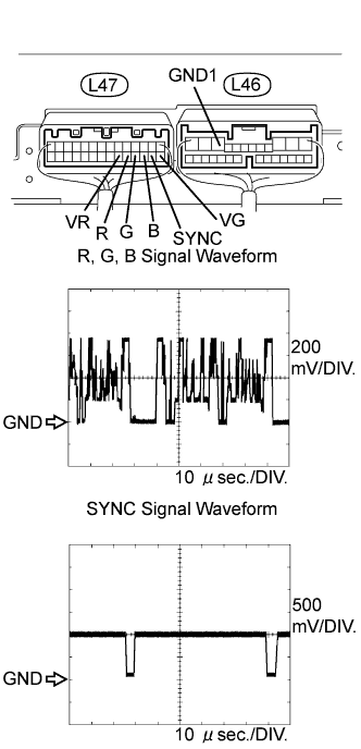
Check the waveform of the multi-display using an oscilloscope.
- Standard voltage:
R, G, B signal waveformTester Connection
| Condition
| Specified Condition
|
L47-19 (R) - L46-10 (GND1)
| Image is displayed
(Rear view monitor system)
| Pulse generation
|
L47-18 (G) - L46-10 (GND1)
|
L47-17 (B) - L46-10 (GND1)
|
SYNC signal waveformTester Connection
| Condition
| Specified Condition
|
L47-16 (SYNC) - L46-10 (GND1)
| Image is displayed
(Rear view monitor system)
| Pulse generation
|
- HINT:
- When trouble occurs in the multi-display, inspect the display signal circuit between the television camera ECU and multi-display (Click here).
| | INSPECT DISPLAY SIGNAL CIRCUIT (TELEVISION CAMERA ECU - MULTI-DISPLAY) |
|
|
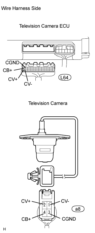
| 2.CHECK WIRE HARNESS (TELEVISION CAMERA ECU - TELEVISION CAMERA) |
Disconnect the L64 ECU connector.
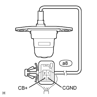
Disconnect the a8 camera connector.
Measure the resistance of the wire harness side connectors.
- Standard resistance:
Tester Connection
| Condition
| Specified Condition
|
L64-20 (CB+) - a8-4 (CB+)
| Always
| Below 1 Ω
|
L64-19 (CGND) - a8-3 (CGND)
| Always
| Below 1 Ω
|
L64-40 (CV+) - a8-2 (CV+)
| Always
| Below 1 Ω
|
L64-39 (CV-) - a8-1 (CV-)
| Always
| Below 1 Ω
|
L64-20 (CB+) - Body ground
| Always
| 10 kΩ or higher
|
L64-19 (CGND) - Body ground
| Always
| 10 kΩ or higher
|
L64-39 (CV+) - Body ground
| Always
| 10 kΩ or higher
|
L64-39 (CV-) - Body ground
| Always
| 10 kΩ or higher
|
| | REPAIR OR REPLACE HARNESS AND CONNECTOR |
|
|
| 3.CHECK TELEVISION CAMERA (POWER SOURCE VOLTAGE) |
Measure the voltage of the connector.
- Standard voltage:
Tester Connection
| Condition
| Specified Condition
|
a8-4 (CB+) - a8-3 (CGND)
| Engine switch on (IG), shift lever in R position
| Approx. 6 V
|
| | REPLACE TELEVISION CAMERA ECU |
|
|
| OK |
|
|
|
| PROCEED TO NEXT CIRCUIT INSPECTION SHOWN IN PROBLEM SYMPTOMS TABLE |
|