Parking Assist Monitor System Television Camera Ecu Power Source Circuit
DESCRIPTION
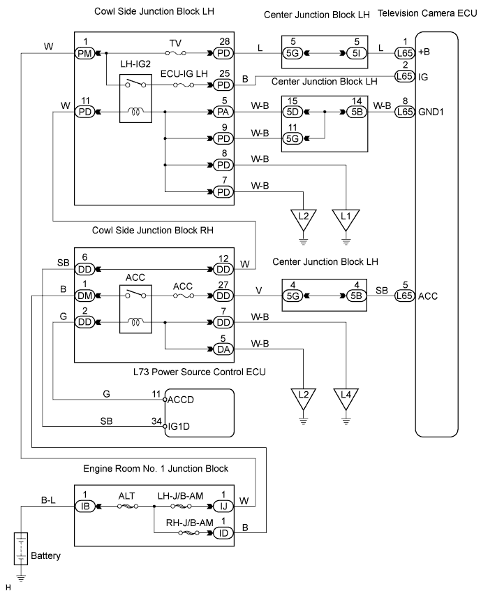
WIRING DIAGRAM
INSPECTION PROCEDURE
INSPECT FUSE (TV, ECU-IG LH, ACC)
CHECK TELEVISION CAMERA ECU (+B, ACC, IG TERMINAL)
CHECK WIRE HARNESS (TELEVISION CAMERA ECU - BODY GROUND)
PARKING ASSIST MONITOR SYSTEM - Television Camera ECU Power Source Circuit |
DESCRIPTION
This circuit provides power to the television camera ECU.
WIRING DIAGRAM
INSPECTION PROCEDURE
| 1.INSPECT FUSE (TV, ECU-IG LH, ACC) |
Remove the TV and ECU-IG LH fuses from the cowl side junction block LH.
Remove the ACC fuse from the cowl side junction block RH.
Measure the resistance of the fuses.
- Standard resistance:
- Below 1 Ω
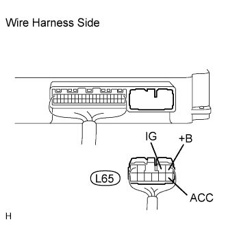
| 2.CHECK TELEVISION CAMERA ECU (+B, ACC, IG TERMINAL) |
Disconnect the L65 ECU connector.
Measure the voltage of the wire harness side connector.
- Standard voltage:
Tester Connection
| Condition
| Specified Condition
|
L65-1 (+B) - Body ground
| Always
| 10 to 14 V
|
L65-5 (ACC) - Body ground
| Engine switch on (ACC)
| 10 to 14 V
|
L65-2 (IG) - Body ground
| Engine switch on (IG)
| 10 to 14 V
|
| | PROCEED TO NEXT CIRCUIT INSPECTION SHOWN IN PROBLEM SYMPTOMS TABLE |
|
|
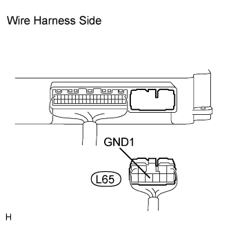
| 3.CHECK WIRE HARNESS (TELEVISION CAMERA ECU - BODY GROUND) |
Disconnect the L65 ECU connector.
Measure the resistance of the wire harness side connector.
- Standard resistance:
Tester Connection
| Condition
| Specified Condition
|
L65-8 (GND1) - Body ground
| Always
| Below 1 Ω
|
| | REPAIR OR REPLACE HARNESS AND CONNECTOR |
|
|
| OK |
|
|
|
| REPAIR OR REPLACE HARNESS AND CONNECTOR (TELEVISION CAMERA ECU - BATTERY) |
|