Navigation System Dimmer Signal Circuit
DESCRIPTION
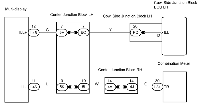
WIRING DIAGRAM
INSPECTION PROCEDURE
CHECK COWL SIDE JUNCTION BLOCK LH
CHECK MULTI-DISPLAY
CHECK WIRE HARNESS (MULTI-DISPLAY - COMBINATION METER)
REPLACE COMBINATION METER
NAVIGATION SYSTEM - Dimmer Signal Circuit |
DESCRIPTION
The multi-display dims by receiving the dimmer signal from the cowl side junction block ECU LH.
WIRING DIAGRAM
INSPECTION PROCEDURE
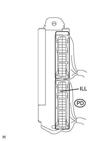
| 1.CHECK COWL SIDE JUNCTION BLOCK LH |
Measure the voltage of the connector.
- Standard voltage:
Tester Connection
| Condition
| Specified Condition
|
PD-20 (ILL) - Body ground
| Light control switch ON
| 10 to 14 V
|
| | REPLACE COWL SIDE JUNCTION BLOCK LH |
|
|
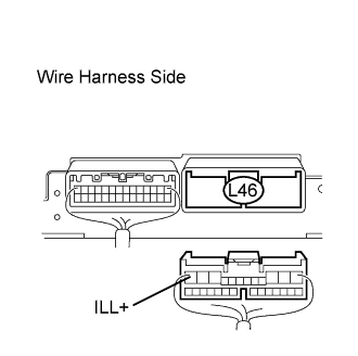
Disconnect the L46 multi-display connector.
Measure the voltage of the wire harness side connector.
- Standard voltage:
Tester Connection
| Condition
| Specified Condition
|
L46-12 (ILL+) - Body ground
| Light control switch ON
| 10 to 14 V
|
| | REPAIR OR REPLACE HARNESS AND CONNECTOR |
|
|
| 3.CHECK WIRE HARNESS (MULTI-DISPLAY - COMBINATION METER) |
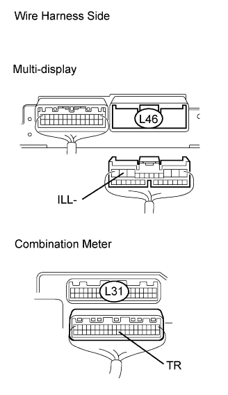
Disconnect the L46 multi-display connector.
Disconnect the L31 meter connector.
Measure the resistance of the wire harness side connectors.
- Standard resistance:
Tester Connection
| Condition
| Specified Condition
|
L46-11 (ILL-) - L31-30 (TR)
| Always
| Below 1 Ω
|
L46-11 (ILL-) - Body ground
| Always
| 10 kΩ or higher
|
| | REPAIR OR REPLACE HARNESS AND CONNECTOR |
|
|
| 4.REPLACE COMBINATION METER |
Replace the combination meter with a normal one and check if the same problem occurs again.
- OK:
- Same problem does not occur.
| OK |
|
|
|
| PROCEED TO NEXT CIRCUIT INSPECTION SHOWN IN PROBLEM SYMPTOMS TABLE |
|