Navigation System -- System Description |
| DIAGNOSIS DISPLAY DETAILED DESCRIPTION (SYSTEM CHECK) |
- HINT:
- This section contains a detailed description of the displays of the diagnostic mode.
- Illustrations may differ from the actual vehicle depending on the device settings and options. Therefore, some detailed areas may not be exactly the same as on the actual vehicle.
System Check Mode Display
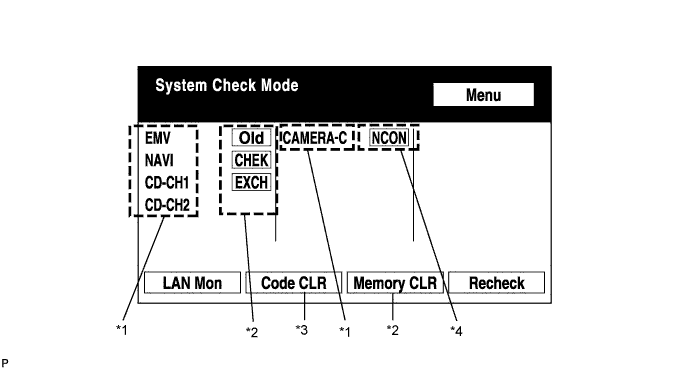
Device Names and Hardware Address / *1
- HINT:
- Registered device names are displayed below.
- If a device name is unknown to the system, its physical address is shown instead.
Address No. Name Address No. Name 110 EMV 120 AVX 128 1DIN TV 140 AVN 144 G-BOOK 178 NAVI 17C MONET 190 AUDIO H/U 1AC CAMERA-C 1B0 Rr-TV 1C0 Rr-CONT 1C2 TV-TUNER2 1C4 PANEL 1C6 G/W 1C8 FM-M-LD 1D8 CONT-SW 1EC BODY 1F0 RADIO TUNER 1F1 XM 1F2 SIRIS 230 TV-TUNER 240 CD-CH2 250 DVD-CH 280 CAMERA 360 CD-CH1 3A0 MD-CH 17D TEL 440 DSP-AMP 530 ETC 5C8 MAYDAY 1A0 DVD-P 1D6 CLOCK 1F4 RSA 1F6 RSE 480 AMP - -
Check Result / *2
- HINT:
- Result codes for all devices are shown below.
Result Meaning Action OK Device did not respond with DTC (excluding communication DTCs from the AVC-LAN) - EXCH Device responds with "replace" type DTC Check DTC in "Unit Check Mode" and replace device CHEK Device responds with "check" type DTC Check DTC in "Unit Check Mode" NCON Device was previously present, but does not respond in diagnostic mode Check power supply wire harness of device
Check AVC-LAN of deviceOld Device responds with "old" type DTC Check DTC in "Unit Check Mode" NRES Device responds in diagnostic mode, but gives no DTC information Check power supply wire harness of device
Check AVC-LAN of the deviceCode Clear / *3
Present DTCs are cleared.Memory Clear / *4
Present and past DTCs and registered connected device names are cleared.
Diagnosis Menu Display
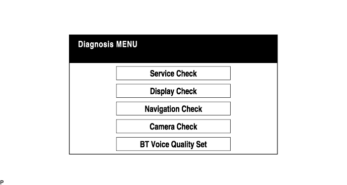
- HINT:
- Each item is grayed out or not displayed based on the device settings.
Unit Check Mode Screen
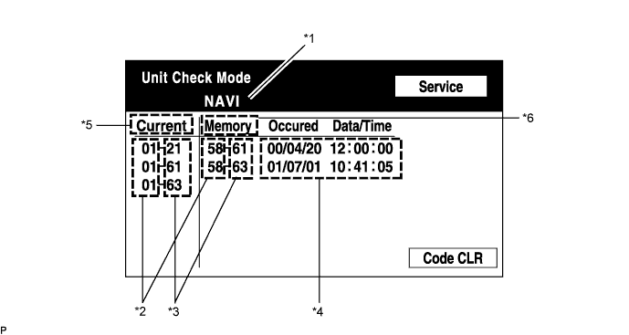
Screen Description Display Contents Device Name / *1 Target device Segment / *2 Target device logical address DTC / *3 DTC (Diagnostic Trouble Code) Time Stamp / *4 Time and date of past DTCs (Year is displayed in 3 digit format) Present Code / *5 DTC output at service check Past Code / *6 Diagnostic memory result and recorded DTCs LAN Monitor (Original) Screen
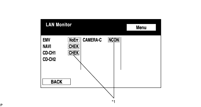
Check result Result Meaning Action No Err
(OK)There are no communication DTCs - CHEK Device responds with a "check" type DTC Check DTC in "Unit Check Mode" NCON The device was previously present, but does not respond in diagnostic mode Check power supply wire harness of device
Check the AVC-LAN of deviceOld The device responded with an "old" type DTC Check DTC in "Unit Check Mode" NRES Device responds in diagnostics mode, but gives no DTC information Check power supply wire harness of device
Check AVC-LAN of device- HINT:
- Check results of all the devices are displayed.
LAN Monitor (Individual) Screen
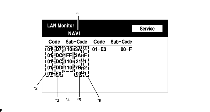
Screen Description Display Contents Device name / *1 Target device Segment / *2 Target logical address DTC / *3 DTC (Diagnostic Trouble Code) Sub-code (device address) / *4 Physical address stored with DTC (If there is no address, nothing is displayed) Connection check No. / *5 Connection check number stored with DTC DTC occurrence / *6 Number of times the same DTC has been recorded
| DIAGNOSIS DISPLAY DETAILED DESCRIPTION (DISPLAY CHECK) |
Vehicle Signal Check Mode Screen

Name Contents Battery Battery voltage is displayed PKB Parking brake ON / OFF state is displayed IG Engine switch ON / OFF state is displayed SPEED Vehicle speed is displayed in km/h TAIL Tail signal (headlight dimmer switch) ON / OFF state is displayed - HINT:
- Only items sending a vehicle signal will be displayed.
- This screen is updated once per second when input signals to the vehicle are changed.
| DIAGNOSIS DISPLAY DETAILED DESCRIPTION (NAVIGATION CHECK) |
Navigation Check MENU Screen
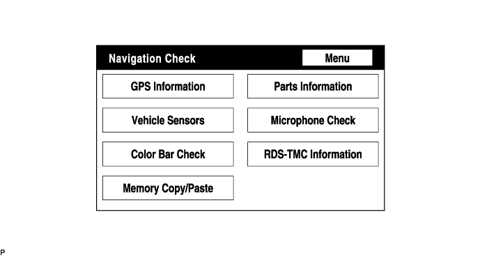
- HINT:
- Each item is grayed out or not displayed based on the device settings.
GPS Information Screen
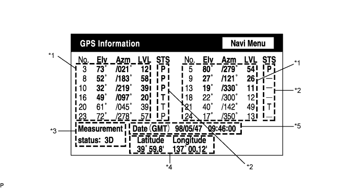
Satellite information / *1
Information from a maximum of 12 satellites is displayed on the screen. This information includes the target GPS satellite number, elevation angle, direction and signal level.Receiving condition / *2
(DENSO made) Display Contents T System is receiving a GPS signal, but is not using it for location P System is using the GPS signal for location - System cannot receive a GPS signal (AISIN made) Display Contents 01H System cannot receive GPS signal 02H System is tracing satellite 03H System is receiving GPS signal, but is not using it for location 04H System is using GPS signal for location Measurement information / *3
Display Contents 2D 2-dimensional location method is being used 3D 3-dimensional location method is being used NG Location data cannot be used Error Reception error has occurred - Any other state Position information / *4
Display Contents Position Latitude and longitude information on current position is displayed Data information / *5
Display Contents Date Date / time information obtained from GPS signal is displayed in Greenwich Mean Time (GMT). Last 4 digits are displayed.
Vehicle Signal Check Screen
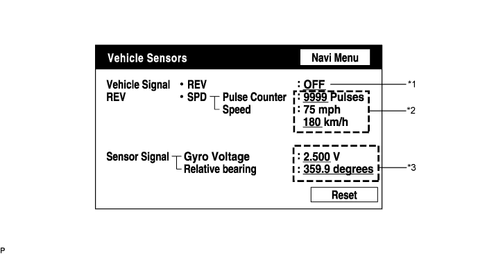
Vehicle signal Display Contents REV / *1 REV signal ON / OFF state is displayed SPD / *2 SPD signal condition is displayed Sensor signal Display Contents Gyro sensor / *3 Gyro sensor output condition is displayed (when the vehicle runs straight or is stationary, voltage is approximately 2.5 V) - HINT:
- Signals are updated once per second only when vehicle sensor signals are changed.
Parts Information Screen
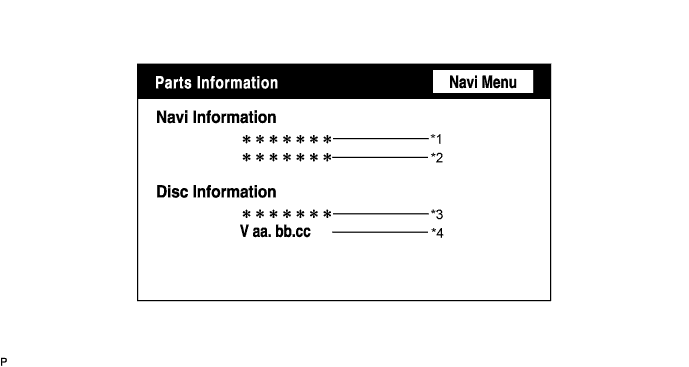
Screen Description Display Contents Navigation Manufacturer / *1 Navigation ECU manufacturer is displayed Navigation Version / *2 Navigation ECU version is displayed Disc Manufacturer / *3 Map disc manufacturer is displayed Disc Manufacturer No. / *4 Map disc version is displayed Memory Copy / Paste Screen
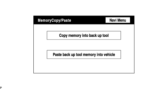
- HINT:
- This function cannot be used on some vehicles.
- When using this function, perform the "Color Bar Check" and "Microphone Check".
- "Color Bar Check" (Click here).
- "Microphone Check" (Click here).
| NAVIGATION SYSTEM OUTLINE |
Vehicle position tracking methods.
It is essential that the navigation system correctly tracks the current vehicle position and displays it on the map. There are 2 methods to track the current vehicle position: autonomous (dead reckoning) and GPS* (satellite) navigation. Both tracking methods are used in conjunction with each other.
- HINT:
- *: GPS (Global Positioning System)
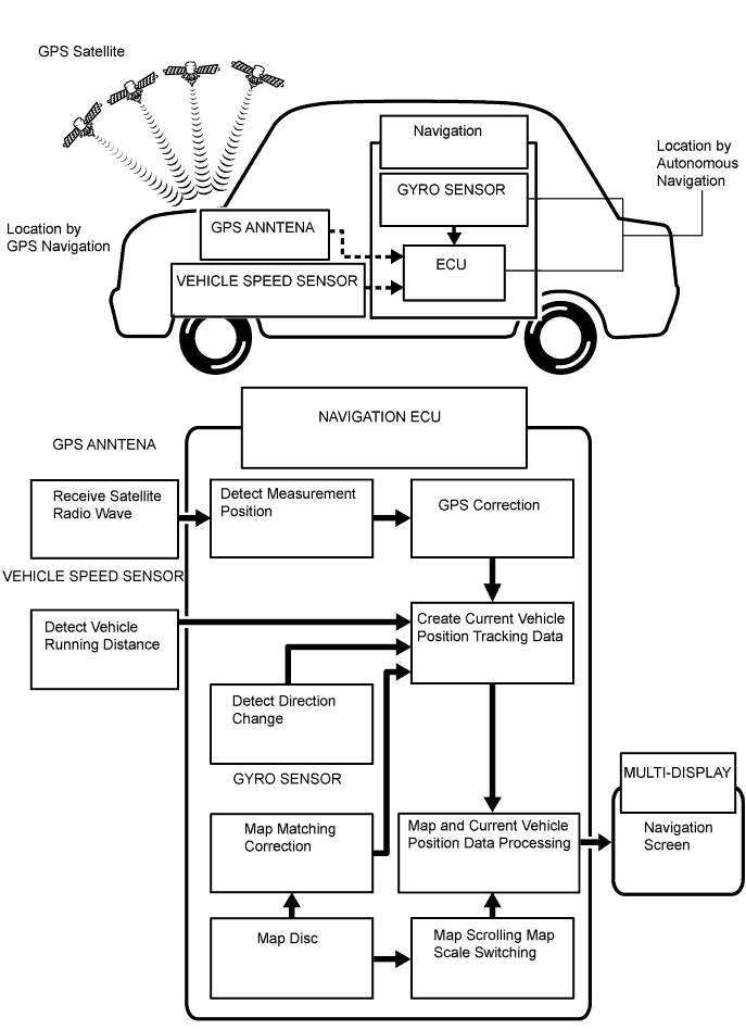
Operation Description Vehicle Position Calculation Navigation ECU calculates current vehicle position (direction and current position) using direction deviation signal from vehicle speed sensor and creates driving route. Map Display Processing Navigation ECU displays vehicle tracking on map by processing vehicle position data, vehicle running track, and map data from map disc. Map Matching Map data from map disc is compared to vehicle position and running track data. Then, vehicle position is matched with nearest road. GPS Correction Vehicle position is matched to position measured by GPS. Then, measurement position data from the GPS is compared with vehicle position and running track data. If position is very different, GPS measurement position is used. Distance Correction Running distance signal from vehicle speed sensor includes errors caused by tire wear and slippage between tires and road surface. Distance correction is performed to account for this. Navigation ECU automatically offsets running distance signal to make up for difference between it and distance data of map. Offset is automatically updated. - HINT:
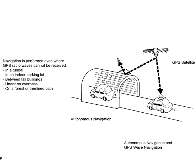
- The combination of autonomous and GPS navigation makes it possible to display the vehicle position even when the vehicle is in a place where GPS radio waves cannot be received. When only autonomous navigation is used, however, the mapping accuracy may slightly decline.
Autonomous navigation
This method determines the relative vehicle position based on the running track determined by the gyro and vehicle speed sensors located in the navigation ECU.Gyro sensor
Calculates the direction by detecting angular velocity. It is located in the radio and navigation assembly.Vehicle speed sensor
Used to calculate the vehicle running distance.
GPS navigation (Satellite navigation)
This method detects the absolute vehicle position using GPS radio waves.- HINT:
- GPS satellites were launched by the U.S. Department of Defense for military purposes.
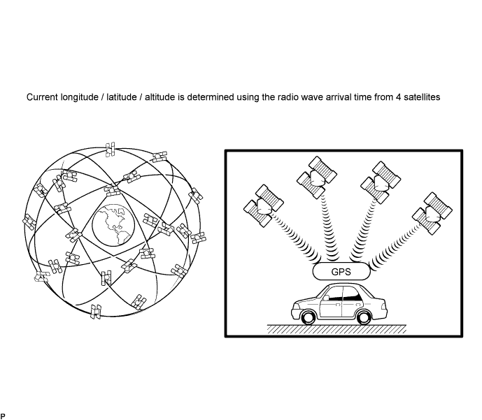
Number of Satellites Measurement Description 2 or less Measurement impossible Vehicle position cannot be obtained because number of satellites is insufficient 3 2-dimensional measurement is possible Vehicle position is obtained based on current longitude and latitude data (This is less precise than 3-dimensional measurement) 4 3-dimensional measurement is possible Vehicle position is obtained based on current longitude, latitude and altitude data Map matching
The current driving route is calculated by autonomous navigation (according to the gyro sensor and vehicle speed sensor) and GPS navigation. This information is then compared with possible road shapes from the map data in the map disc and the vehicle position is set onto the most appropriate road.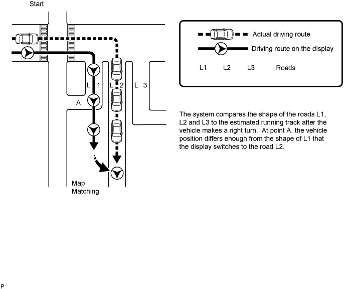
| DVD (DIGITAL VERSATILE DISC) PLAYER OUTLINE (FOR NAVIGATION MAP) |
The navigation ECU uses a laser pickup to read the digital signals recorded on a DVD.
- CAUTION:
- Because the navigation system uses an invisible laser beam, do not look directly at the laser pickup. Be sure to only operate the navigation as instructed.
- HINT:
- Do not disassemble any part of the navigation ECU.
- Do not apply oil to the navigation ECU.
- Do not insert anything but DVDs into the navigation ECU.
| MULTI-DISPLAY OUTLINE |
Touch switch
Touch switches are touch-sensitive (interactive) switches operated by touching the screen. When a switch is pressed, the outer glass bends in to contact the inner glass at the pressed position. By doing this, the voltage ratio is measured and the pressed position is detected.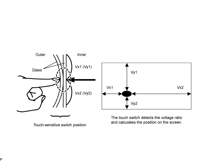
| AVC-LAN DESCRIPTION |
What is AVC-LAN?
AVC-LAN, an abbreviation for "Audio Visual Communication Local Area Network", is a united standard developed by the manufacturers in affiliation with Toyota Motor Corporation. This standard pertains to audio and visual signals as well as switch and communication signals.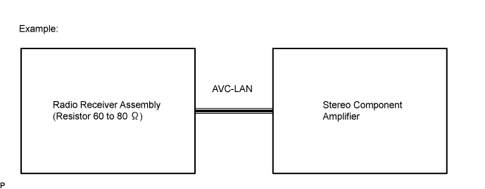
Purpose:
Recently, car audio systems have rapidly developed and the functions have vastly changed. The conventional car audio system is being integrated with a multimedia interface similar to those in navigation systems. At the same time, customers are demanding higher quality from their audio systems. This is an overview of the AVC-LAN standardization. Its specific purposes are as follows:To solve sound problems, etc., caused by using components of different manufacturers through signal standardization.
To allow each manufacturer to concentrate on developing products they do best. From this, reasonably priced products can be produced.
- HINT:
- If a +B or GND short is detected in the AVC-LAN circuit, communication is interrupted and the audio system will stop functioning.
- If an audio system is equipped with a navigation system, the multi-display unit acts as the master unit. If a navigation system is not equipped, the audio head unit acts as the master unit instead.
- The radio receiver assembly provides resistance to make communication possible.
- A car audio system with an AVC-LAN circuit has a diagnostic function.
- Each component has a specified number (3-digit) called a physical address. Each function has a number (2-digit) called a logical address.
- Components of the navigation system communicate with each other via the AVC-LAN.
| BLUETOOTH ONLINE |
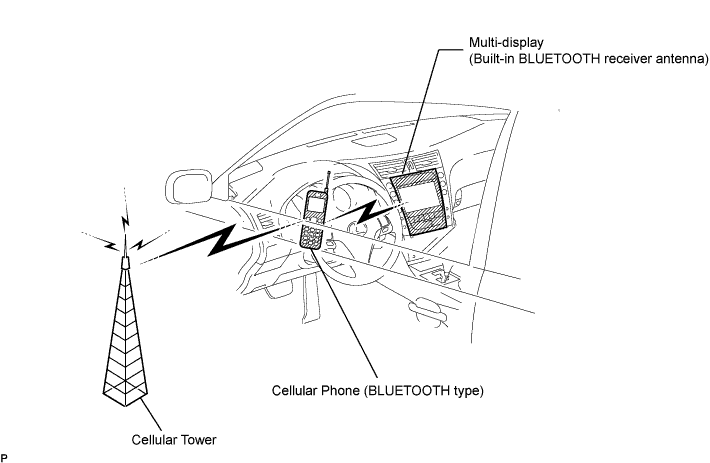
BLUETOOTH is a wireless connection technology that uses the 2.4 GHz frequency band. This makes it possible to remotely connect a cellular phone (BLUETOOTH-capable phone) to the multi-display (BLUETOOTH system is built-in), and use a hands-free function with the cellular phone even when it is in your pocket or bag.
- HINT:
- Some versions of BLUETOOTH may vary depending on obstructions or radio wave conditions between communication devices, electromagnetic radiation, communication device sensitivity, or antenna capacity.
| SYSTEM NORMAL CONDITION CHECK |
If a symptom is applicable to any of the following, it is not a malfunction.
Symptom Answer A longer route than expected is chosen Depending on road conditions, navigation ECU may determine that longer route is quicker Even when distance priority is high, shortest route is not shown Some paths may not be chosen due to safety concerns When the vehicle is put into motion immediately after engine start, the navigation system deviates from actual position If vehicle starts before navigation system activates, system may not react When running on certain types of roads, especially new roads, vehicle position deviates from actual position When vehicle is driving on new roads not available on map disc, system attempts to match it to another nearby road, causing position mark to deviate The following symptoms are not a malfunction, but are caused by errors inherent in the GPS, gyro sensor, speed sensor, and navigation ECU.
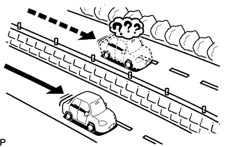
The current position mark may be displayed on a nearby parallel road.
Immediately after a fork in the road, the current vehicle position mark may be displayed on the wrong road.
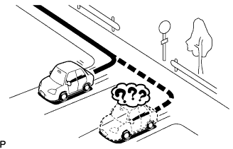
When the vehicle turns right or left at an intersection, the current vehicle position mark may be displayed on a nearby parallel road.
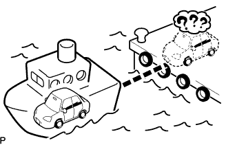
When the vehicle is transported, such as on a ferry, and the vehicle itself is not running, the current vehicle position mark may be displayed in the position where the vehicle was until a measurement is performed by the GPS.
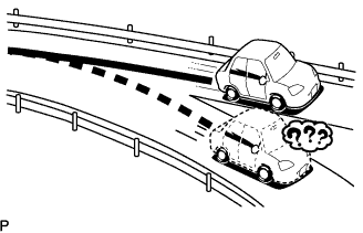
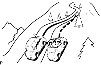
When the vehicle runs on a steep hill, the current vehicle position mark may deviate from the correct position.
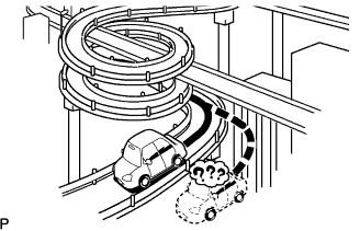
When the vehicle makes a continuous turn of 360°, 720°, 1,080°, etc., the current vehicle position mark may deviate from the correct position.
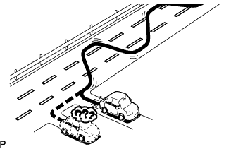
When the vehicle moves erratically, such as during constant lane changes, the current vehicle position mark may deviate from the correct position.
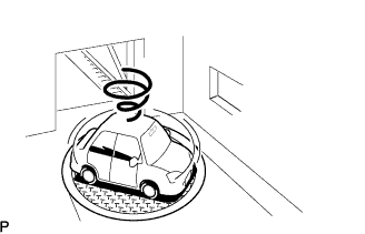
When the engine switch is turned on (ACC) / off while on a turntable before parking, the current vehicle position mark may not point in the correct direction. The same will occur when the vehicle comes out of parking.
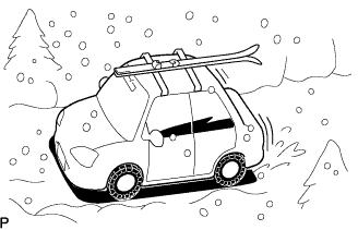
When the vehicle is driven on a snowy road or mountain path with chains installed or a spare tire installed, the current vehicle position mark may deviate from the correct position.
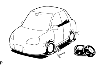
When a tire is changed, the current vehicle position mark may deviate from the correct position.
- HINT:
- The diameter of the tire may change, causing a speed sensor error.
- Performing the "tire change" in calibration mode will allow the system to correct the current vehicle position faster.