Heater & Air Conditioning System. Lexus Gs430, Gs300. Uzs190 Grs190
Air Conditioning. Lexus Gs430, Gs300. Uzs190 Grs190
Air Conditioning System -- Terminals Of Ecu |
| CHECK AIR CONDITIONING AMPLIFIER |

- HINT:
- Check from the rear of the connector while it is connected to the A/C amplifier.
| Symbols (Terminal No.) | Wiring Color | Terminal Description | Condition | Specified Condition |
| B (L52-1) - Body ground | L - Body ground | Power source (Back-up) | Always | 10 to 14 V |
| HT2 (L52-2) - Body ground | R - Body ground | GLW RLY2 relay signal | Engine running at 850 rpm or more, ambient temperature 3°C (37.4°F) or less, engine coolant temperature 75°C (167°F) or less, A/C switch setting MAX HOT, blower switch Lo | 10 to 14 V |
| SOL+ (L52-5) - Body ground | R - Body ground | A/C compressor operation signal | A/C magnetic clutch to ON | Pulse generation (see waveform 1) |
| S5-1 (L52-7) - SG-1 (L52-19) | P - B | Power supply for room temperature sensor | Engine switch: off | Below 1.0 V |
| Engine switch: on (IG) | 5 V | |||
| BLW (L52-11) - GND (L52-20) | G - W-B | Blower motor control signal | Engine switch: on (IG) Blower switch: OFF → ON | Pulse generation (see waveform 2) |
| PRE (L52-13) - SG-2 (L52-38) | W - V | Pressure sensor signal | Start engine, operate A/C system Refrigerant pressure: Abnormal pressure (more than 3,030 kPa (31.0 kgf/cm2, 440 psi)) | 4.7 V or higher |
| PRE (L52-13) - SG-2 (L52-38) | W - V | Pressure sensor signal | Start engine, operate A/C system Refrigerant pressure: Abnormal pressure (less than 180 kPa (1.9 kgf/cm2, 27 psi)) | Below 0.7 V |
| PRE (L52-13) - SG-2 (L52-38) | W - V | Pressure sensor signal | Start engine, operate A/C system Refrigerant pressure: Abnormal pressure (more than 3,030 kPa (31.0 kgf/cm2, 440 psi) and more than 180 kPa (1.9 kgf/cm2, 27 psi)) | 0.7 to 4.7 V |
| TSP (L52-14) - GND (L52-20) | P - W-B | Passenger side solar sensor signal | Engine switch: on (IG) Solar sensor subject to electric light | 0.8 to 4.3 V |
| RH (L52-15) - SG-1 (L52-19) | SB - B | Humidity sensor signal | Engine switch on (IG), vehicle interior temperature 25°C (77°F), vehicle interior humidity 40 to 60% | 40%: 1.61 to 2.24 V 60%: 2.26 to 2.66 V |
| TR (L52-16) - SG-1 (L52-19) | BR - B | Room temperature sensor signal | Engine switch on (IG), vehicle interior temperature 25°C (77°F) | 1.8 to 2.2 V |
| GND (L52-18) - VOUT (L52-32) | P - GR | Low pressure sensor signal | Start engine, operate A/C system Refrigerant pressure: Abnormal pressure (more than 980 kPa (10.0 kgf/cm2, 142 psi) and more than 180 kPa (1.9 kgf/cm2, 27 psi)) | 1.1 to 4.6 V |
| SG-1 (L52-19) - Body ground | B - Body ground | Ground for room temperature sensor (built-in humidity sensor) | Always | Below 1.0 Ω |
| GND (L52-20) - Body ground | W-B - Body ground | Ground for main power supply | Always | Below 1.0 Ω |
| IG+ (L52-21) - Body ground | W - Body ground | Power source (IG) | Engine switch: off or on (ACC) | Below 1.0 V |
| Engine switch: on (IG) | 10 to 14 V | |||
| S5-2 (L52-26) - SG-2 (L52-38) | Y - V | Power supply for pressure sensor | Engine switch: on (IG) A/C switch: OFF | Below 1.0 V |
| Engine switch: on (IG) A/C switch: ON | 5 V | |||
| VC (L52-27) - VOUT (L52-32) | O - GR | Power supply for low pressure sensor | Engine switch: on (IG) A/C switch: OFF | Below 1.0 V |
| Engine switch: on (IG) A/C switch: ON | 5 V | |||
| MPX+ (L52-30) | SB | Multiplex communication system | Multiplex communication circuit | - |
| MPX- (L52-31) | Y | Multiplex communication system | Multiplex communication circuit | - |
| VOUT (L52-32) - Body ground | GR - Body ground | Ground for low pressure sensor | Always | Below 1.0 Ω |
| DGS1 (L52-33) - SG-6 (L52-39) | R - CR | Exhaust gas sensor signal (NOx) | After 30 seconds from engine switch on (IG) and sensor is exposed to exhaust gas | 1.0 to 4.5 V |
| DGS (L52-34) - SG-6 (L52-39) | L - CR | Exhaust gas sensor signal (HC, CO) | After 30 seconds from engine switch on (IG) and sensor is exposed to exhaust gas | 1.0 to 4.5 V |
| TSD (L52-35) - GND (L52-20) | LG - W-B | Driver side solar sensor signal | Engine switch: on (IG) Solar sensor subject to electric light | 0.8 to 4.3 V |
| SG-2 (L52-38) - Body ground | V - Body ground | Ground for pressure sensor | Always | Below 1.0 Ω |
| SG-6 (L52-39) - Body ground | CR - Body ground | Ground for exhaust gas sensor | Always | Below 1.0 Ω |
| HT1 (L51-13) - Body ground | Y - Body ground | GLW RLY1 relay signal | Engine running at 850 rpm or more, ambient temperature 3°C (37.4°F) or less, engine coolant temperature 75°C (167°F) or less, A/C switch setting MAX HOT, blower switch Lo | 10 to 14 V |
| BUSG (e1-2) - Body ground | - | Ground for BUS IC | Always | Below 1.0 Ω |
| BUS (e1-3) - BUSG (e1-2) | - | BUS IC control signal | Engine switch: off → on (IG) | Pulse generation |
| BBUS (e1-4) - BUSG (e1-2) | - | Power supply for BUS IC | Engine switch: off | Below 1.0 V |
| Engine switch: on (IG) | 10 to 14 V | |||
| SG-10 (e1-5) - BUSG (e1-2) | - | Ground for evaporator temperature sensor | Always | Below 1.0 Ω |
| TE (e1-6) - SG-10 (e1-5) | - | Evaporator temperature sensor signal | Engine switch on (IG), temperature near evaporator is 15°C (59°F) | 1.4 to 1.8 V |
Waveform 1:
Item Contents Symbols (Terminal No.) SOL+ (L52-5) - Body ground Tool Setting 5 V / DIV., 500 μs / DIV. Vehicle Condition A/C magnetic clutch ON Waveform 2:
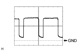
Item Contents Symbols (Terminal No.) BLW (L52-11) - GND (L52-20) Tool Setting 1 V / DIV., 500 μs / DIV. Vehicle Condition Engine switch: on (IG)
Blower switch: OFF → ON- HINT:
- When the blower level is increased, the duty ratio changes accordingly.
 |
 |