Body Electrical. Lexus Gs430, Gs300. Uzs190 Grs190
Lighting. Lexus Gs430, Gs300. Uzs190 Grs190
Lighting System -- Terminals Of Ecu |
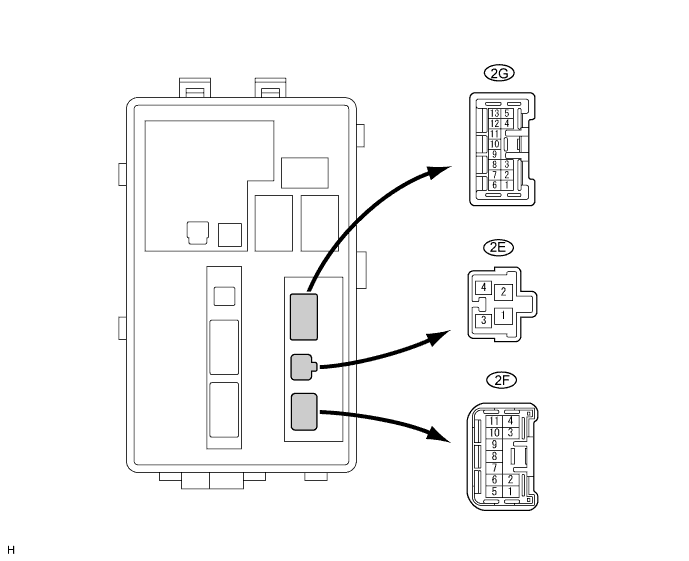
| CHECK ENGINE ROOM NO. 2 RELAY BLOCK (FRONT CONTROLLER) |
| Symbols (Terminal No.) | Wiring Color | Terminal Description | Condition | Specified Condition |
| ALTB (2E-1) - Body ground | W - Body ground | Power source circuit | Always | 10 to 14 V |
| BATB (2E-2) - Body ground | W-L - Body ground | Power source circuit | Always | 10 to 14 V |
| FMIG (2E-3) - Body ground | B-Y - Body ground | Engine switch signal circuit | Engine switch on (IG) | 10 to 14 V |
| FMIG (2E-3) - Body ground | B-Y - Body ground | Engine switch signal circuit | Engine switch off | Below 1 V |
| FMB3 (2E-4) - Body ground | G-R - Body ground | Power source circuit | Always | 10 to 14 V |
| E (2F-1) - Body ground | W-B - Body ground | Ground | Always | Below 1 V |
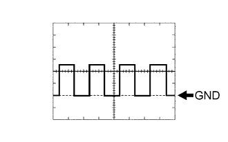
| MPX1 (2F-5) - Body ground | GR-L - Body ground | Multiplex communication signal circuit | Engine switch on (IG) | Signal waveform |
| MPX2 (2F-6) - Body ground | GR-L - Body ground | Multiplex communication signal circuit | Engine switch on (IG) | Signal waveform |
| FOGR (2G-6) - Body ground | G-Y - Body ground | Fog light circuit (To front fog light RH) | Front fog light ON | 10 to 14 V |
| FOGR (2G-6) - Body ground | G-Y - Body ground | Fog light circuit (To front fog light RH) | Front fog light OFF | Below 1 V |
| FOGL (2G-7) - Body ground | G-R - Body ground | Fog light circuit (To front fog light LH) | Front fog light ON | 10 to 14 V |
| FOGL (2G-7) - Body ground | G-R - Body ground | Fog light circuit (To front fog light LH) | Front fog light OFF | Below 1 V |
| CRAR (2G-8) - Body ground | G - Body ground | Taillight circuit (To clearance light RH) | Light control switch in TAIL | 10 to 14 V |
| CRAR (2G-8) - Body ground | G - Body ground | Taillight circuit (To clearance light RH) | Light control switch OFF | Below 1 V |
| CRAL (2G-9) - Body ground | G - Body ground | Taillight circuit (To clearance light LH) | Light control switch in TAIL | 10 to 14 V |
| CRAL (2G-9) - Body ground | G - Body ground | Taillight circuit (To clearance light LH) | Light control switch OFF | Below 1 V |
| HLHR (2G-12) - Body ground | R-W - Body ground | Hi-beam circuit (To headlight RH) | Headlight dimmer switch in HI | 10 to 14 V |
| HLHR (2G-12) - Body ground | R-W - Body ground | Hi-beam circuit (To headlight RH) | Headlight dimmer switch in HEAD | Below 1 V |
| HLHL (2G-13) - Body ground | R-Y - Body ground | Hi-beam circuit (To headlight LH) | Headlight dimmer switch in HI | 10 to 14 V |
| HLHL (2G-13) - Body ground | R-Y - Body ground | Hi-beam circuit (To headlight LH) | Headlight dimmer switch in HEAD | Below 1 V |
| CHECK COWL SIDE JUNCTION BLOCK LH ECU |
| Symbols (Terminal No.) | Wiring Color | Terminal Description | Condition | Specified Condition |
| GND (PA-14) - Body ground | W-B - Body ground | Ground | Always | Below 1 V |
| TR (PA-26) - Body ground | B - Body ground | RH side turn signal (To turn signal flasher assembly) | Engine switch off | Below 1 V |
| TR (PA-26) - Body ground | B - Body ground | RH side turn signal (To turn signal flasher assembly) | Engine switch on (IG) and turn signal switch (right turn) ON | 10 to 14 V (60 to 120 times per minute) |
| TL (PA-25) - Body ground | L - Body ground | LH side turn signal (To turn signal flasher assembly) | Engine switch off | Below 1 V |
| TL (PA-25) - Body ground | L - Body ground | LH side turn signal (To turn signal flasher assembly) | Engine switch on (IG) and turn signal switch (left turn) ON | 10 to 14 V (60 to 120 times per minute) |
| SGND (PD-7) - Body ground | W-B - Body ground | Ground | Always | Below 1 V |
| SGND (PD-8) - Body ground | W-B - Body ground | Ground | Always | Below 1 V |
| IG (15) - Body ground | - | Engine switch signal circuit | Engine switch on (IG) | 10 to 14 V |
| IG (15) - Body ground | - | Engine switch signal circuit | Engine switch off | Below 1 V |
| MPX-B (PL-1) - Body ground | G-R - Body ground | Multiplex communication power source circuit | Always | 10 to 14 V |
| ILE (W1-2) - Body ground | L - Body ground | Illumination signal (To front room light) | Room light switch in DOOR position and room light comes on | Below 1 V |
| ILE (V1-2) - Body ground | L - Body ground | Illumination signal (To front room light) | Room light switch in DOOR position and room light comes on | 10 to 14 V |
| RCTY (W1-3) - Body ground | Y - Body ground | Illumination signal (To room light rear RH) | Spot light rear RH comes on | Below 1 V |
| RCTY (W1-3) - Body ground | Y - Body ground | Illumination signal (To room light rear RH) | Room light rear RH goes off | 10 to 14 V |
| LCTY (W1-4) - Body ground | SB - Body ground | Illumination signal (To room light rear LH) | Room light rear LH comes on | Below 1 V |
| LCTY (W1-4) - Body ground | SB - Body ground | Illumination signal (To room light rear LH) | Room light rear LH goes off | 10 to 14 V |
| MPX1 (W3-15) - Body ground | GR - Body ground | Multiplex communication signal circuit | Engine switch on (IG) | Signal waveform |
| CHECK MULTIPLEX NETWORK BODY ECU |
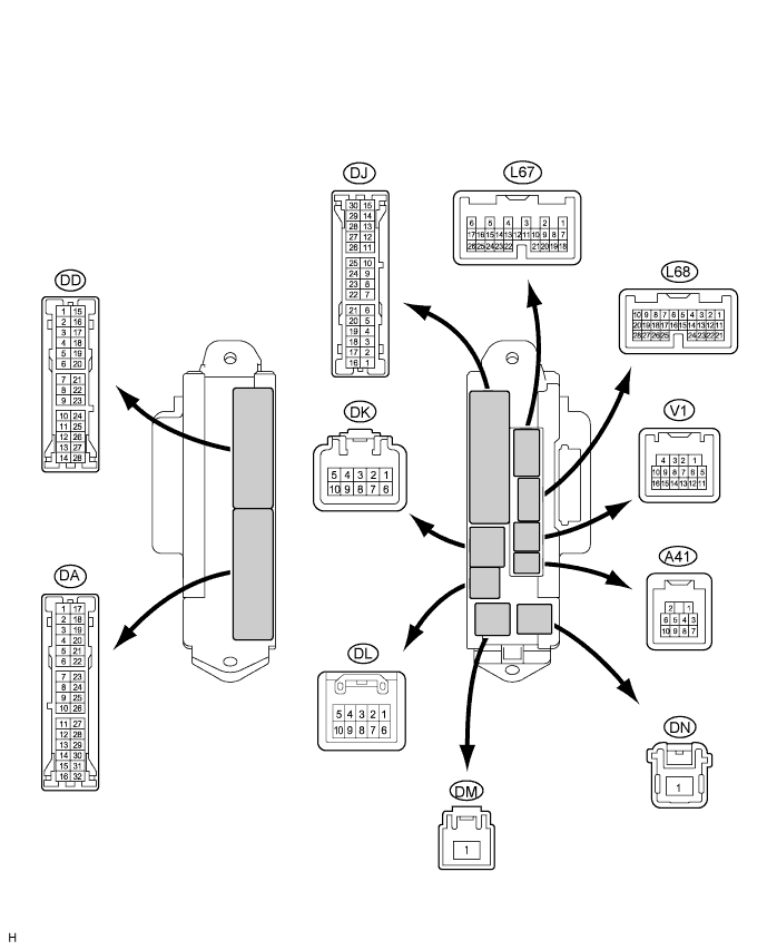
| Symbols (Terminal No.) | Wiring Color | Terminal Description | Condition | Specified Condition |
| GND2 (DD-7) - Body ground | W-B - Body ground | Ground | Always | Below 1 V |
| LCTY (DA-11) - Body ground | G - Body ground | Illumination signal (From courtesy switch rear LH) | Rear LH door is closed | 10 to 14 V |
| LCTY (DA-11) - Body ground | G - Body ground | Illumination signal (From courtesy switch rear LH) | Rear LH door is open | Below 1 V |
| MPX1 (DA-26) - Body ground | GR - Body ground | Multiplex communication signal circuit | Engine switch on (IG) | Signal waveform |
| GND2 (DD-7) - Body ground | W-B - Body ground | Ground | Always | Below 1 V |
| IG (15) - Body ground | - | Engine switch signal circuit | Engine switch on (IG) | 10 to 14 V |
| IG (15) - Body ground | - | Engine switch signal circuit | Engine switch off | Below 1 V |
| ACC (22) - Body ground | - | Engine switch on (ACC) signal circuit | Engine switch off | Below 1 V |
| ACC (22) - Body ground | - | Engine switch on (ACC) signal circuit | Engine switch on (ACC) | 10 to 14 V |
| BECU (DK-5) - Body ground | G-R - Body ground | Multiplex communication power source circuit | Always | 10 to 14 V |
| HRLY (DL-7) - Body ground | R - Body ground | HEAD signal (To HEAD relay) | Light control switch OFF or in TAIL | 10 to 14 V |
| HRLY (DL-7) - Body ground | R - Body ground | HEAD signal (To HEAD relay) | Light control switch in HEAD | Below 1 V |
| DCTY (V1-14) - Body ground | R - Body ground | Illumination signal (From driver side courtesy) | Driver's side door is closed | 10 to 14 V |
| DCTY (V1-14) - Body ground | R - Body ground | Illumination signal (From driver side courtesy) | Driver's side door is open | Below 1 V |
| RCTY (V1-16) - Body ground | L - Body ground | Illumination signal (From courtesy switch rear RH) | Rear door is closed | 10 to 14 V |
| RCTY (U1-16) - Body ground | L - Body ground | Illumination signal (From courtesy switch rear RH) | Rear door is open | Below 1 V |
| FSPT (L68-15) - Body ground | Y - Body ground | Illumination signal (To foot lights) | Foot lights come on | Below 1 V |
| FSPT (L68-15) - Body ground | Y - Body ground | Illumination signal (To foot lights) | Foot lights go off | 10 to 14 V |
| MPX2 (L68-21) - Body ground | G - Body ground *1 | Multiplex communication signal circuit | Engine switch on (IG) | Signal waveform |
| O - Body ground *2 | Multiplex communication signal circuit | Engine switch on (IG) | Signal waveform | |
| RCTY (V1-16) - Body ground | L - Body ground | Illumination signal (From courtesy switch front LH) | Passenger's side door is closed | 10 to 14 V |
| PCTY (L68-23) - Body ground | R - Body ground | Illumination signal (From courtesy switch front LH) | Passenger's side door is open | Below 1 V |
| HAZ (L67-2) - Body ground | O - Body ground | HAZARD signal (From hazard switch) | Hazard switch OFF | 10 to 14 V |
| HAZ (L67-2) - Body ground | O - Body ground | HAZARD signal (From hazard switch) | Hazard switch ON | Below 1 V |
| CLTE (K67-4) - Body ground | BR - Body ground | Automatic light control sensor ground circuit | Always | Below 1 V |
| CLTS (L67-5) - Body ground | R - Body ground | Automatic light control sensor ground circuit | Engine switch off | Below 1 V |
| CLTS (L67-5) - Body ground | R - Body ground | Automatic light control sensor ground circuit | Engine switch on (IG), light control switch in AUTO, headlight comes on | Signal waveform |
| CLTB (L67-6) - Body ground | W - Body ground | Automatic light control sensor power source circuit | Engine switch off | Below 1 V |
| CLTB (L67-6) - Body ground | W - Body ground | Automatic light control sensor power source circuit | Engine switch on (IG) | 10 to 14 V |
| HEAD (L67-23) - Body ground | G - Body ground | HEAD signal (From light control switch) | Light control switch OFF or TAIL | 10 to 14 V |
| HEAD (L67-23) - Body ground | G - Body ground | HEAD signal (From light control switch) | Light control switch in HEAD | Below 1 V |
- HINT:
- *1: LHD
- *2: RHD
| CHECK MULTIPLEX NETWORK REAR ECU |
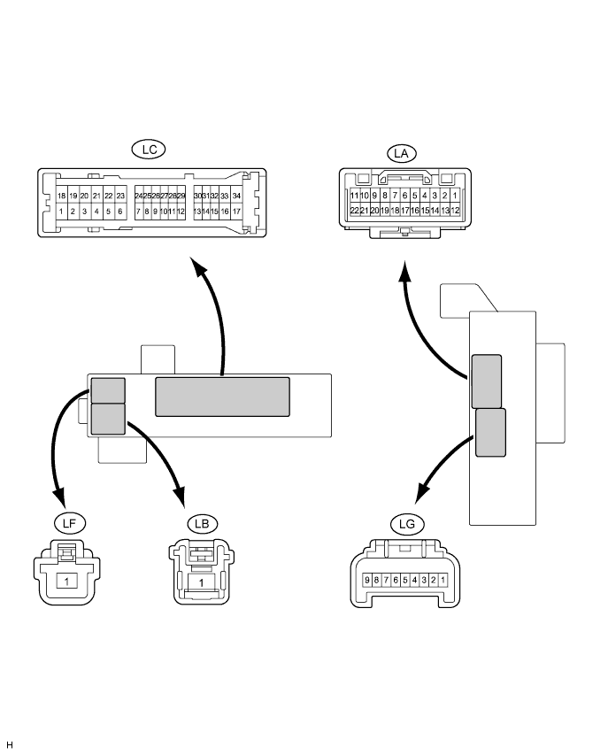
| Symbols (Terminal No.) | Wiring Color | Terminal Description | Condition | Specified Condition |
| BCK1 (LA-2) - Body ground | R - Body ground | Back-up light signal (To luggage compartment door side rear combination light LH and RH) | Engine switch off | Below 1 V |
| BCK1 (LA-2) - Body ground | R - Body ground | Back-up light signal (To luggage compartment door side rear combination light LH and RH) | Engine switch on (IG) and shift lever in R position | 10 to 14 V |
| PGND (LF-1) - Body ground | W-B - Body ground | Ground | Always | Below 1 V |
| PGND (LF-1) - Body ground | W-B - Body ground | Ground | Always | Below 1 V |
| TIL2 (LA-8) - Body ground | V - Body ground | Taillight signal (To luggage compartment door side rear combination light LH) | Light control switch OFF | Below 1 V |
| TIL2 (LA-8) - Body ground | V - Body ground | Taillight signal (To luggage compartment door side rear combination light LH) | Light control switch in TAIL | 10 to 14 V |
| LCE1 (LA-10) - Body ground | GR - Body ground | Taillight signal (To license plate light LH and RH) | Light control switch OFF | Below 1 V |
| LCE1 (LA-10) - Body ground | GR - Body ground | Taillight signal (To license plate light LH and RH) | Light control switch in TAIL | 10 to 14 V |
| TIL1 (LA-22) - Body ground | BR - Body ground | Taillight signal (To luggage compartment door side rear combination light RH) | Light control switch OFF | Below 1 V |
| TIL1 (LA-22) - Body ground | BR - Body ground | Taillight signal (To luggage compartment door side rear combination light RH) | Light control switch in TAIL | 10 to 14 V |
| +BR (2) | - | Power source circuit | Always | 10 to 14 V |
| SG (LC-3) - Body ground | W-B - Body ground | Ground | Always | Below 1 V |
| ECUB (LC-15) - Body ground | B - Body ground | Multiplex communication power source circuit | Always | 10 to 14 V |
| MPX1 (LC-21) - Body ground | BR - Body ground | Multiplex communication power source circuit | Engine switch on (IG) | Signal waveform |
| IG (8) - Body ground | - | Power source circuit | Engine switch on (IG) | 10 to 14 V |
| MPX2 (LC-31) - Body ground | GR - Body ground | Multiplex communication power source circuit | Engine switch on (IG) | Signal waveform |
| STP1 (LA-4) - Body ground | B - Body ground | Stop light switch signal | Brake pedal is released | Below 1 V |
| STP1 (LA-4) - Body ground | B - Body ground | Stop light switch signal | Brake pedal is depressed | 10 to 14 V |
| PGND (LF-1) - Body ground | W-B - Body ground | Ground | Always | Below 1 V |
| TIL2 (LA-8) - Body ground | V - Body ground | Taillight signal (To body side rear combination light LH) | Light control switch OFF | Below 1 V |
| TIL2 (LA-8) - Body ground | V - Body ground | Taillight signal (To body side rear combination light LH) | Light control switch in TAIL | 10 to 14 V |
| STP2 (LG-7) - Body ground | W - Body ground | Taillight signal (To body side rear combination light LH and RH) | Brake pedal is released | Below 1 V |
| STP2 (LG-7) - Body ground | W - Body ground | Taillight signal (To body side rear combination light LH and RH) | Brake pedal is depressed | 10 to 14 V |
| BCK1 (LA-2) - Body ground | R - Body ground | Back-up light signal (To body side rear combination light LH and RH) | Engine switch off | Below 1 V |
| BCK1 (LA-2) - Body ground | R - Body ground | Back-up light signal (To body side rear combination light LH and RH) | Engine switch on (IG) and shift lever in R position | 10 to 14 V |
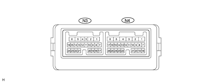
| CHECK MULTIPLEX NETWORK DOOR ECU FRONT LH |

| Symbols (Terminal No.) | Wiring Color | Terminal Description | Condition | Specified Condition |
| GND (O3-1) - Body ground | W-B - Body ground | Ground | Always | Below 1 V |
| SIG (O3-3) - GND (O3-1) | Y - W-B | Power source circuit (From battery) | Engine switch off | Below 1 V |
| SIG (O3-3) - GND (O3-1) | Y - W-B | Power source circuit (From battery) | Engine switch on (IG) | 10 to 14 V |
| CPUB (O3-4) - GND (O3-1) | LG - W-B | Power source circuit (From battery) | Always | 10 to 14 V |
| BDR (O3-6) - GND (O3-1) | L - W-B | Power source circuit (From battery) | Always | 10 to 14 V |
| MPX1 (O3-8) - Body ground | P - Body ground | Multiplex communication signal circuit | Engine switch on (IG) | Signal waveform |
| MPX2 (O3-9) - Body ground | L - Body ground | Multiplex communication signal circuit | Engine switch on (IG) | Signal waveform |
| CTYB (O3-12) - CYL (O3-11) | L - R | Illumination signal (To door courtesy light front LH) | Front LH side door is closed | Below 1 V |
| CTYB (O3-12) - CYL (O3-11) | L - R | Illumination signal (To door courtesy light front LH) | Front LH side door is open | 10 to 14 V |
| LED+ (O3-14) - LED-(O3-13) | W - W-B | Inside handle illumination signal (Inside handle illumination front LH) | Front LH side door is closed | Below 1 V |
| LED+ (O3-14) - LED-(O3-13) | W - W-B | Inside handle illumination signal (Inside handle illumination front LH) | Front LH side door is open | 10 to 14 V |
| CHECK MULTIPLEX NETWORK DOOR ECU FRONT RH |
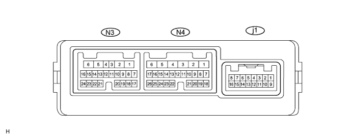
| Symbols (Terminal No.) | Wiring Color | Terminal Description | Condition | Specified Condition |
| GND (N4-1) - Body ground | W-B - Body ground | Ground | Always | Below 1 V |
| SIG (N4-3) - GND (N4-1) | L - W-B | Power source circuit (From battery) | Engine switch off | Below 1 V |
| SIG (N4-3) - GND (N4-1) | L - W-B | Power source circuit (From battery) | Engine switch on (IG) | 10 to 14 V |
| CPUB (N4-4) - GND (N4-1) | LG - W-B | Power source circuit (From battery) | Always | 10 to 14 V |
| BDR (N4-6) - GND (N4-1) | L - W-B | Power source circuit (From battery) | Always | 10 to 14 V |
| MPX1 (N3-8) - Body ground | GR - Body ground | Multiplex communication signal circuit | Engine switch on (IG) | Signal waveform |
| MPX2 (N4-9) - Body ground | P - Body ground | Multiplex communication signal circuit | Engine switch on (IG) | Signal waveform |
| CTYB (N4-12) - CYL (N3-11) | L - R | Illumination signal (To door courtesy light front RH) | Front RH side door is closed | Below 1 V |
| CTYB (N4-12) - CYL (N4-11) | L - R | Illumination signal (To door courtesy light front RH) | Front RH side door is open | 10 to 14 V |
| LED+ (N4-14) - LED-(N4-13) | P- W-B | Inside handle illumination signal (Inside handle illumination front RH) | Front RH side door is closed | Below 1 V |
| LED+ (N4-14) - LED-(N4-13) | P - W-B | Inside handle illumination signal (Inside handle illumination front RH) | Front RH side door is open | 10 to 14 V |
| LSW (N3-14) - LSWE (N3-13) | G - LG | Door lock position circuit | Front RH side door is locked | 10 to 14 V |
| LSW (N3-14) - LSWE (N3-13) | G - LG | Door lock position circuit | Front RH side door is unlocked | Below 1 V |
| CHECK MULTIPLEX NETWORK DOOR ECU REAR LH |

| Symbols (Terminal No.) | Wiring Color | Terminal Description | Condition | Specified Condition |
| GND (Q2-1) - Body ground | W-B - Body ground | Ground | Always | Below 1 V |
| SIG (Q2-3) - GND (Q2-1) | G - W-B | Power source circuit (From battery) | Engine switch off | Below 1 V |
| SIG (Q2-3) - GND (Q2-1) | G - W-B | Power source circuit (From battery) | Engine switch on (IG) | 10 to 14 V |
| CPUB (Q2-4) - GND (Q2-1) | BR - W-B | Power source circuit (From battery) | Always | 10 to 14 V |
| BDR (Q2-6) - GND (Q2-1) | L - W-B | Power source circuit (From battery) | Always | 10 to 14 V |
| MPX1 (Q2-8) - Body ground | GR - Body ground | Multiplex communication signal circuit | Engine switch on (IG) | Signal waveform |
| MPX2 (Q2-9) - Body ground | P - Body ground | Multiplex communication signal circuit | Engine switch on (IG) | Signal waveform |
| CTYB (Q2-12) - CYL (Q2-11) | L - R | Illumination signal (To door courtesy light front LH) | Rear LH side door is closed | 10 to 14 V |
| CTYB (Q2-12) - CYL (Q2-11) | L - R | Illumination signal (To door courtesy light front LH) | Rear LH side door is open | Below 1 V |
| LED+ (Q2-14) - LED- (Q2-13) | V - W-B | Illumination signal (To ashtray illumination rear LH) | Rear LH side door is open | 10 to 14 V |
| LED+ (Q2-14) - LED- (Q2-13) | V - W-B | Illumination signal (To ashtray illumination rear LH) | Rear LH side door is closed | Below 1 V |
| LSW (Q3-14) - LSWE (Q3-13) | LG - W-B | Door lock position circuit | Rear LH door is locked | 10 to 14 V |
| LSW (Q3-14) - LSWE (Q3-13) | LG - W-B | Door lock position circuit | Rear LH door is unlocked | Below 1 V |
| CHECK MULTIPLEX NETWORK DOOR ECU REAR RH |
| Symbols (Terminal No.) | Wiring Color | Terminal Description | Condition | Specified Condition |
| GND (N4-1) - Body ground | W-B - Body ground | Ground | Always | Below 1 V |
| SIG (N4-3) - GND (N4-1) | L - W-B | Power source circuit (From battery) | Engine switch off | Below 1 V |
| SIG (N4-3) - GND (N4-1) | L - W-B | Power source circuit (From battery) | Engine switch on (IG) | 10 to 14 V |
| CPUB (N4-4) - GND (N4-1) | G - W-B | Power source circuit (From battery) | Always | 10 to 14 V |
| BDR (N4-6) - GND (N4-1) | L - W-B | Power source circuit (From battery) | Always | 10 to 14 V |
| MPX1 (N4-8) - Body ground | GR - Body ground | Multiplex communication signal circuit | Engine switch on (IG) | Signal waveform |
| MPX2 (N4-9) - Body ground | P - Body ground | Multiplex communication signal circuit | Engine switch on (IG) | Signal waveform |
| CTYB (N4-12) - CYL (N4-11) | L - R | Illumination signal (To door courtesy light front RH) | Rear RH side door is closed | 10 to 14 V |
| CTYB (N4-12) - CYL (N4-11) | L - R | Illumination signal (To door courtesy light front RH) | Rear RH side door is open | Below 1 V |
| LED+ (N4-14) - LED- (N4-13) | P - W-B | Illumination signal (To ashtray illumination rear LH) | Rear RH side door is closed | 10 to 14 V |
| LED+ (N4-14) - LED- (N4-13) | P - W-B | Illumination signal (To ashtray illumination rear LH) | Rear RH side door is open | Below 1 V |
| LSW (N3-14) - LSWE (N3-13) | G - LG | Door lock position circuit | Rear RH door is locked | 10 to 14 V |
| LSW (N3-14) - LSWE (N3-13) | G - LG | Door lock position circuit | Rear RH door is unlocked | Below 1 V |
| CHECK COMBINATION SWITCH ASSEMBLY (WINDSHIELD WIPER SWITCH) |

| Symbols (Terminal No.) | Wiring Color | Terminal Description | Condition | Specified Condition |
| B (L22-1) - E (L22-5) | GR - W-B | Power source circuit (From battery) | Always | 10 to 14 V |
| IG (L22-2) - E (L22-5) | LG - W-B | Engine switch signal circuit (From engine switch) | Engine switch off | Below 1 V |
| IG (L22-2) - E (L22-5) | LG - W-B | Engine switch signal circuit (From engine switch) | Engine switch on (IG) | 10 to 14 V |
| HEAD (L22-4) - Body ground | V - Body ground | Light control switch HEAD signal | Light control switch not in HEAD | 10 to 14 V |
| HEAD (L22-4) - Body ground | V - Body ground | Light control switch HEAD signal | Light control switch in HEAD | Below 1 V |
| E (L22-5) - Body ground | W-B - Body ground | Ground | Always | Below 1 V |
| MPX1 (L22-6) - Body ground | G - Body ground*1 | Multiplex communication signal circuit | Engine switch on (IG) | Signal waveform |
| O - Body ground*2 | ||||
| MPX2 (L22-7) - Body ground | O - Body ground*1 | Multiplex communication signal circuit | Engine switch on (IG) | Signal waveform |
| R - Body ground*2 |
- HINT:
- *1: LHD
- *2: RHD
| CHECK AFS ECU |
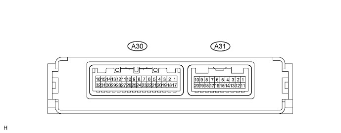
| Symbols (Terminal No.) | Wiring Color | Terminal Description | Condition | Specified Condition |
| SBF (A30-1) - SGF (A20-17) | G-R - G | Vehicle height signal (To height control sensor) | Engine switch off | Below 1 V |
| Engine switch on (IG) | 4.5 V to 5.5 V | |||
| SHFL (A30-2) - SGF (A30-17) | G-B - G | Vehicle height signal (To height control sensor) | Engine switch off | Below 1 V |
| Engine switch on (IG), the vehicle is still or bounced | 0.5 V to 4.5 V | |||
| SPDL (A30-6) - E1 (A31-1) | R-L - W-B | Vehicle speed signal (To skid control ECU) | Vehicle is driving at approx. 30 km/h (19 mph) | Pulse generation (see waveform 1) |
| SPDR (A30-7) - E1 (A31-1) | G-W - W-B | Vehicle speed signal (To skid control ECU) | Vehicle is driving at approx. 30 km/h (19 mph) | Pulse generation (see waveform 1) |
| BR1+ (A30-9) - BR1- (A30-10) | LG-R - O | Headlight swivel motor RH | Engine switch off | Below 1 V |
| Engine running, light control switch in HEAD, driving at more than 10 km/h (6 mph) and turning the steering wheel to right more than 7.5° | Pulse generation (see waveform 2) | |||
| BR2+ (A30-11) - BR2- (A30-12) | L-B - L-Y | Headlight swivel motor RH | Engine switch off | Below 1 V |
| Engine running, light control switch in HEAD, driving at more than 10 km/h (6 mph) and turning the steering wheel to right more than 7.5° | Pulse generation (see waveform 2) | |||
| LR1+ (A30-13) - LR1- (A30-14) | L - BR-W | Headlight leveling actuator RH | Engine switch off | Below 1 V |
| Engine running, light control switch in HEAD, the vehicle is standing still or bounding | Pulse generation (see waveform 3) | |||
| LR2+ (A30-15) - LR2- (A30-16) | P - LG | Headlight leveling actuator RH | Engine switch off | Below 1 V |
| Engine running, light control switch in HEAD, the vehicle is standing still or bounding | Pulse generation (see waveform 3) | |||
| SGF (A30-17) - E1 (A31-1) | G - W-B | Vehicle height signal (To height control sensor) | Always | Below 1 V |
| SMGR (A30-18) - E1 (A31-1) | W-R - W-B | Headlight swivel motor RH | Always | Below 1 V |
| SMGL (A30-19) - E1 (A31-1) | P-G - W-B | Headlight swivel motor LH | Always | Below 1 V |
| SMBR (A30-21) - SMGR (A30-18) | GR - W-R | Headlight swivel motor RH | Engine switch off | Below 1 V |
| Engine switch on (IG) | 4.5 V to 5.5 V | |||
| SMBL (A30-22) - SMGL (A30-19) | W - P-G | Headlight swivel motor LH | Engine switch off | Below 1 V |
| Engine switch on (IG) | 4.5 V to 5.5 V | |||
| SMR (A30-23) - SMGR (A30-18) | G-B - W-R | Headlight swivel motor RH | Engine switch off | Below 1 V |
| Engine switch on (IG) | 0.3 V to 4.6 V | |||
| SML (A30-24) - SMGL (A30-19) | Y - P-G | Headlight swivel motor LH | Engine switch off | Below 1 V |
| Engine switch on (IG) | 0.3 V to 4.6 V | |||
| BL1+ (A30-25) - BL1-(A30-26) | B-L - L-W | Headlight swivel motor LH | Engine switch off | Below 1 V |
| Engine running, light control switch in HEAD, driving at more than 10 km/h (6 mph) and turning the steering wheel to left more than 7.5° | Pulse generation (see waveform 2) | |||
| BL2+ (A30-27) - BL2-(A30-28) | L-R - V | Headlight swivel motor LH | Engine switch off | Below 1 V |
| Engine running, light control switch in HEAD, driving at more than 10 km/h (6 mph) and turning the steering wheel to left more than 7.5° | Pulse generation (see waveform 2) | |||
| LL1+ (A30-29) - LL1-(A30-30) | R-G - G | Headlight leveling actuator LH | Engine switch off | Below 1 V |
| Engine running, light control switch in HEAD, the vehicle is still or bounced | Pulse generation (see waveform 3) | |||
| LL2+ (A30-31) - LL2-(A30-32) | Y-R - V-R | Headlight leveling actuator LH | Engine switch off | Below 1 V |
| Engine running, light control switch in HEAD, the vehicle is standing still or bouncing | Pulse generation (see waveform 3) | |||
| E1 (A31-1) - Body ground | W-B - Body ground | Ground | Always | Below 1 V |
| IG (A31-2) - E1 (A31-1) | B - Body ground | Power source circuit (To engine switch) | Engine switch off | Below 1 V |
| Engine switch on (IG) | 10 to 14 V | |||
| MPX1 (A31-5) - E1 (A31-1) | - | Multiplex communication signal | Engine switch on (IG) | Signal waveform |
| MPX2 (A31-6) - E1 (A31-1) | - | Multiplex communication signal | Engine switch on (IG) | Signal waveform |
| SS+ (A31-7) - SS- (A31-8) *1 | L - Y | Steering sensor signal (To position sensor) | Engine idling, slowly turn steering wheel | Pulse generation |
| SS+ (A31-7) - SS- (A31-8) *2 | L - LG | Steering sensor signal (To steering control ECU) | Engine idling, slowly turn steering wheel | Pulse generation |
| SHRL (A31-9) - SGR (A31-20) | B-W - R-Y | Vehicle height signal (To height control sensor rear) | Engine switch off | Below 1 V |
| Engine switch on (IG), bounce the vehicle | 0.5 to 4.5 V | |||
| SBR (A30-10) - SGR (A30-20) | W - R-Y | Vehicle height signal (To height control sensor rear) | Engine switch off | Below 1 V |
| Engine switch on (IG) | 4.5 to 5.5 V | |||
| SBF (A30-1) - SGF (A30-17) | G-R - G | Vehicle height signal (To height control sensor front) | Engine switch off | Below 1 V |
| Engine switch on (IG) | 4.5 to 5.5 V | |||
| SBR (A31-10) - SGR (A31-20) | W - R-Y | Vehicle height signal (To height control sensor rear) | Always | Below 1 V |
| SBF (A30-1) - SGF (A30-17) | G-R - G | Vehicle height signal (To height control sensor front) | Always | Below 1 V |
- HINT:
- *1: 3UZ-FE
- *2: 3GR-FE, 3GR-FSE
Waveform 1
Item Contents Symbols (Terminal No.) SPDL(A30-6) - E1(A31-1)
SPDR(A30-7) - E1(A31-1)Vehicle Condition Vehicle is driving at approximately 30 km/h (19 mph) Waveform 2
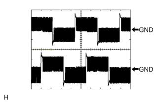
Item Contents Symbols (Terminal No.) BL1+(A30-25) - BL1-(A30-26)
BL2+(A30-27) - BL2-(A30-28)
BR1+(A30-9) - BR1-(A30-10)
BR2+(A30-11) - BR2-(A30-12)Tool Setting 10 V / DIV., 5 msec. / DIV. Vehicle Condition - Engine running, light control switch in HEAD, driving at more than 10 km/h (6 mph) and turning the steering wheel more than 7.5°
- If value is not within standard range, it is possible there is some defect on vehicle side
Inspect fuse, wire harness and connector
- Engine running, light control switch in HEAD, driving at more than 10 km/h (6 mph) and turning the steering wheel more than 7.5°
Waveform 3
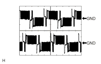
Item Contents Symbols (Terminal No.) LR1+(A30-13) - LR1-(A30-14)
LR2+(A30-15) - LR2-(A30-16)
LL1+(A30-29) - LL1-(A30-30)
LL2+(A30-31) - LL2-(A30-32)Tool Setting 10 V / DIV., 5 msec. / DIV. Vehicle Condition - Engine running, light control switch in HEAD, driving at more than 10 km/h (6 mph) and turning the steering wheel more than 7.5°
- If value is not within standard range, it is possible there is some defect on vehicle side
Inspect fuse, wire harness and connector
- Engine running, light control switch in HEAD, driving at more than 10 km/h (6 mph) and turning the steering wheel more than 7.5°
 |
 |
 |