Dtc P2118 Throttle Actuator Control Motor Current Range / Performance
Engine. Lexus Gs430, Gs300. Uzs190 Grs190
DESCRIPTION
MONITOR DESCRIPTION
FAIL-SAFE
WIRING DIAGRAM
INSPECTION PROCEDURE
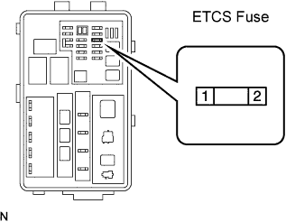
INSPECT FUSE (ETCS)
READ DATA LIST (+BM VOLTAGE)
CHECK WIRE HARNESS (ECM - ETCS FUSE, ETCS FUSE - BATTERY)
DTC P2118 Throttle Actuator Control Motor Current Range / Performance |
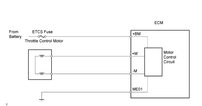
DESCRIPTION
The Electronic Throttle Control System (ETCS) has a dedicated power supply circuit. The voltage (+BM) is monitored and when the voltage is low (less than 4 V), the ECM concludes that the ETCS has a fault and current to the throttle actuator is cut.When the voltage becomes unstable, the ETCS itself becomes unstable. For this reason, when the voltage is low, the current to the throttle actuator is cut. If repairs are made and the system has returned to normal, turn the engine switch off. The ECM then allows current to flow to the throttle actuator so that the engine can be restarted.- HINT:
- The ETCS does not use a throttle cable.
DTC No.
| DTC Detection Conditions
| Trouble Areas
|
P2118
| Open in ETCS power source (+BM) circuit
(1 trip detection logic)
| - Open in ETCS power source circuit
- ETCS fuse
- ECM
|
MONITOR DESCRIPTION
The ECM monitors the battery supply voltage applied to throttle actuator.When the power supply voltage (+BM) drops below 4 V for 0.8 seconds or more, the ECM interprets this as an open in the power supply circuit (+BM). The ECM illuminates the MIL and sets a DTC.This monitor runs for 5 seconds (the first 5 seconds of engine idle) after the engine is started.
FAIL-SAFE
If the ETCS has a malfunction, the ECM cuts off current to the throttle actuator. The throttle valve returns to a predetermined opening angle (approximately 16°) by the force of the return spring. The ECM then adjusts the engine output by controlling the fuel injection (intermittent fuel-cut) and ignition timing in accordance with the accelerator pedal opening angle to enable the vehicle to continue at a minimal speed.If the accelerator pedal is depressed firmly and slowly, the vehicle can be driven slowly.If a "pass" condition is detected and then the engine switch is turned off, the fail-safe operation will stop and the system will return to normal.
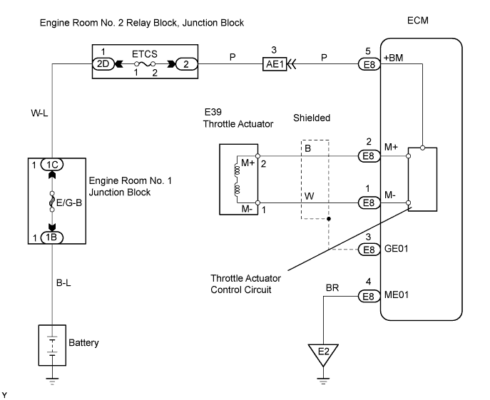
WIRING DIAGRAM
INSPECTION PROCEDURE
- HINT:
- Read freeze frame data using the intelligent tester. Freeze frame data records the engine conditions when a malfunction is detected. When troubleshooting, freeze frame data can help determine if the vehicle was running or stopped, if the engine was warmed up or not, if the air-fuel ratio was LEAN or RICH, and other data from the time the malfunction occurred.
Remove the ETCS fuse from the engine room No. 2 relay block.
Measure the resistance of the fuse.
- Standard resistance:
- Below 1 Ω
| 2.READ DATA LIST (+BM VOLTAGE) |
Connect the intelligent tester to the DLC3.
Turn the engine switch on (IG).
Enter the following menus: Powertrain / Engine / Data List / Primary / +BM Voltage.
- Standard voltage:
- 9 to 14 V
| | CHECK FOR INTERMITTENT PROBLEM |
|
|
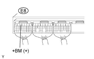
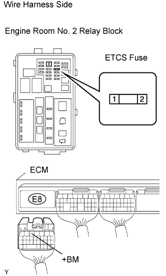
| 3.CHECK WIRE HARNESS (ECM - ETCS FUSE, ETCS FUSE - BATTERY) |
Remove the ETCS fuse from the engine room No. 2 relay block, junction block.
Disconnect the E8 ECM connector.
Measure the resistance of the wire harness side connectors.
- Standard resistance:
Tester Connection
| Specified Condition
|
Relay block ETCS fuse terminal 1 - Battery positive (+) terminal
| Below 1 Ω
|
Relay block ETCS fuse terminal 2 - E8-5 (+BM)
| Below 1 Ω
|
Relay block ETCS fuse terminal 1 or Battery positive (+) terminal - Body ground
| 10 kΩ or higher
|
Relay block ETCS fuse terminal 2 or E8-5 (+BM) - Body ground
| 10 kΩ or higher
|
| | REPAIR OR REPLACE HARNESS AND CONNECTOR |
|
|