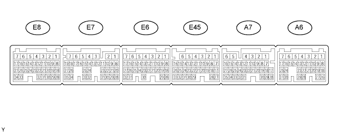
Symbols (Terminal No.)
| Wiring Color
| Terminal Description
| Condition
| Specified Condition
|
BATT (A6-4) - E1 (E7-7)
| L - BR
| Battery (for measuring battery voltage and for ECM memory)
| Always
| 9 to 14 V
|
+BM (E8-5) - E1 (E7-7)
| P - BR
| Power source of throttle motor
| Always
| 9 to 14 V
|
IGSW (A6-17) - E1 (E7-7)
| B-W - BR
| Engine switch
| Engine switch on (IG)
| 9 to 14 V
|
+B (A6-6) - E1 (E7-7)
| B-R - BR
| Power source of ECM
| Engine switch on (IG)
| 9 to 14 V
|
+B1 (A6-5) - E1 (E7-7)
| B-R - BR
| Power source of ECM
| Engine switch on (IG)
| 9 to 14 V
|
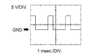
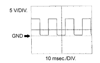
OC1+ (E8-34) - OC1- (E8-33)
| W - Y-B
| Camshaft timing oil control valve (OCV) (Intake side (bank 1))
| Engine switch on (IG)
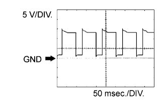
| Pulse generation (see waveform 1)
|
OC2+ (E6-9) - OC2- (E6-8)
| LG - L-B
| Camshaft timing oil control valve (OCV) (Intake side (bank 2))
| Engine switch on (IG)
| Pulse generation (see waveform 1)
|
OE1+ (E8-9) - OE1- (E8-8)
| LG - L-W
| Camshaft timing oil control valve (OCV) (Exhaust side (bank 1))
| Engine switch on (IG)
| Pulse generation (see waveform 1)
|
OE2+ (E6-24) - OE2- (E6-23)
| R-R - G-B
| Camshaft timing oil control valve (OCV) (Exhaust side (bank 2))
| Engine switch on (IG)
| Pulse generation (see waveform 1)
|
MREL (A6-13) - E1 (E7-7)
| Y - BR
| EFI MAIN relay
| Engine switch on (IG)
| 9 to 14 V
|
VC (E8-29) - E2 (E8-28)
| L - BR
| Power source for sensors (specific voltage)
| Engine switch on (IG)
| 4.5 to 5.0 V
|
VC2 (E6-29) - E3 (E6-30)
| L-Y - BR
| Power source for sensors (specific voltage)
| Engine switch on (IG)
| 4.5 to 5.0 V
|
VG (E6-27) - E2G (E6-26)
| G-B - B-W
| Mass air flow meter
| Idling, Shift lever position P or N, A/C switch OFF
| 0.5 to 3.0 V
|
THA (E6-25) - E3 (E6-30)
| G - BR
| Intake air temperature sensor
| Idling, Intake air temperature 20°C (68°F)
| 0.5 to 3.4 V
|
THW (E6-20) - E2 (E8-28)
| R - BR
| Engine coolant temperature sensor
| Idling, Engine coolant temperature 80°C (176°F)
| 0.2 to 1.0 V
|
VTA1 (E8-23) - E3 (E6-30)
| R-B - BR
| Throttle position sensor (for engine control)
| Engine switch on (IG), Throttle valve fully closed
| 0.5 to 1.2 V
|
VTA1 (E8-23) - E3 (E6-30)
| R-B - BR
| Throttle position sensor (for engine control)
| Engine switch on (IG), Throttle valve fully open
| 3.2 to 4.8 V
|
VTA2 (E8-22) - E3 (E6-30)
| L-B - BR
| Throttle position sensor (for sensor malfunction detection)
| Engine switch on (IG), Accelerator pedal released
| 2.1 to 3.1 V
|
VTA2 (E8-22) - E3 (E6-30)
| L-B - BR
| Throttle position sensor (for sensor malfunction detection)
| Engine switch on (IG), Accelerator pedal depressed
| 4.5 to 5.0 V
|
VPA (A7-33) - EPA (A7-34)
| G-W - L-Y
| Accelerator pedal position sensor (for engine control)
| Engine switch on (IG), Accelerator pedal released
| 0.5 to 1.1 V
|
VPA (A7-33) - EPA (A7-34)
| G-W - L-Y
| Accelerator pedal position sensor (for engine control)
| Engine switch on (IG), Accelerator pedal depressed
| 2.6 to 4.5 V
|
VPA2 (A7-32) - EPA2 (A7-26)
| P-L - BR
| Accelerator pedal position sensor (for sensor malfunctioning detection)
| Engine switch on (IG), Accelerator pedal released
| 1.2 to 2.0 V
|
VPA2 (A7-32) - EPA2 (A7-26)
| P-L - BR
| Accelerator pedal position sensor (for sensor malfunctioning detection)
| Engine switch on (IG), Accelerator pedal depressed
| 3.4 to 5.0 V
|
VCPA (A7-35) - EPA2 (A7-26)
| P - BR
| Power source of accelerator pedal position sensor (for VPA)
| Engine switch on (IG)
| 4.5 to 5.0 V
|
VCP2 (A7-27) - EPA2 (A7-26)
| LG - BR
| Power source of accelerator pedal position sensor (for VPA2)
| Engine switch on (IG)
| 4.5 to 5.0 V
|
HA1A (E45-6) - E04 (E45-5)
| V - W-B
| A/F sensor heater
| Idling
| Below 3.0 V
|
HA2A (E45-4) - E05 (E45-3)
| B-L - W-B
| A/F sensor heater
| Idling
| Below 3.0 V
|
HA1A (E45-6) - E04 (E45-5)
| V - W-B
| A/F sensor heater
| Engine switch on (IG)
| 9 to 14 V
|
HA2A (E45-4) - E05 (E45-3)
| B-L - W-B
| A/F sensor heater
| Engine switch on (IG)
| 9 to 14 V
|
A1A+ (E45-18) - E1 (E7-7)
| R - BR
| A/F sensor
| Engine switch on (IG)
| 3.3 V*
|
A2A+ (E45-28) - E1 (E7-7)
| B - BR
| A/F sensor
| Engine switch on (IG)
| 3.3 V*
|
A1A- (E45-17) - E1 (E7-7)
| G - BR
| A/F sensor
| Engine switch on (IG)
| 3.0 V*
|
A2A- (E45-27) - E1 (E7-7)
| W - BR
| A/F sensor
| Engine switch on (IG)
| 3.0 V*
|
HT1B (A7-2) - E1 (E7-7)
| Y-B - BR
| Heated oxygen sensor heater
| Idling
| Below 3.0 V
|
HT2B (A7-1) - E1 (E7-7)
| L-W - BR
| Heated oxygen sensor heater
| Idling
| Below 3.0 V
|
HT1B (A7-2) - E1 (E7-7)
| Y-B - BR
| Heated oxygen sensor heater
| Engine switch on (IG)
| 9 to 14 V
|
HT2B (A7-1) - E1 (E7-7)
| L-W - BR
| Heated oxygen sensor heater
| Engine switch on (IG)
| 9 to 14 V
|
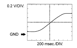
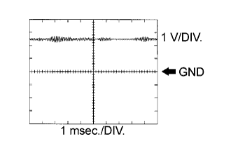
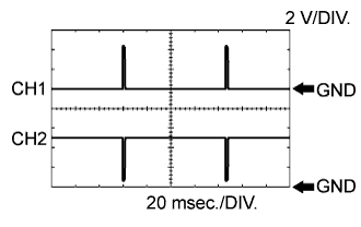
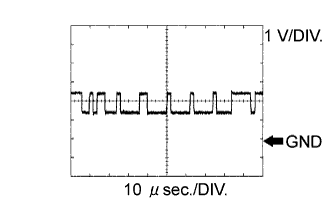
OX1B (A7-28) - O1B- (A7-29)
| R - G
| Heated oxygen sensor
| Maintain engine speed at 2,500 rpm for 2 minutes after warming up sensor
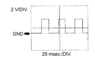
| Pulse generation (see waveform 2)
|
OX2B (A7-17) - O2B- (A7-18)
| B - W
| Heated oxygen sensor
| Maintain engine speed at 2,500 rpm for 2 minutes after warming up sensor
| Pulse generation (see waveform 2)
|
#10 (E8-15) - E1 (E7-7)
#20 (E6-17) - E1 (E7-7)
#30 (E8-14) - E1 (E7-7)
#40 (E6-16) - E1 (E7-7)
#50 (E8-13) - E1 (E7-7)
#60 (E6-15) - E1 (E7-7)
| G-W - BR
B-Y - BR
P-L - BR
LG-B - BR
V - BR
R-B - BR
| Injector
| Engine switch on (IG)
| 0 to 5 V
|
#10 (E8-15) - E1 (E7-7)
#20 (E6-17) - E1 (E7-7)
#30 (E6-14) - E1 (E7-7)
#40 (E6-16) - E1 (E7-7)
#50 (E8-13) - E1 (E7-7)
#60 (E6-15) - E1 (E7-7)
| G-W - BR
B-Y - BR
P-L - BR
LG-B - BR
V - BR
R-B - BR
| Injector
| Idling
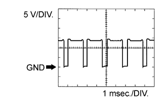
| Pulse generation (see waveform 3)
|
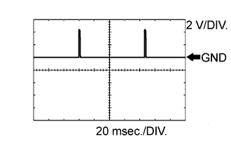
KNK1 (E7-28) - EKNK (E7-30)
| B - W
| Knock sensor
| Maintain engine speed at 4,000 after warming up
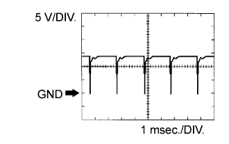
| Pulse generation (see waveform 4)
|
KNK2 (E7-29) - EKN2 (E7-31)
| R - G
| Knock sensor
| Maintain engine speed at 4,000 after warming up
| Pulse generation (see waveform 4)
|
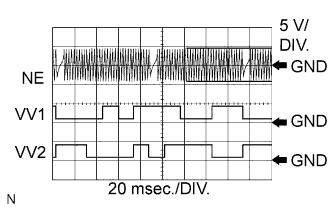
VV1+ (E8-21) - VV1- (E8-20)
| Y - L-Y
| Variable valve timing (VVT) sensor (Intake side (bank 1))
| Idling
| Pulse generation (see waveform 5)
|
VV2+ (E8-19) - VV2- (E8-18)
| R-L - W
| Variable valve timing (VVT) sensor (Intake side (bank 2))
| Idling
| Pulse generation (see waveform 5)
|
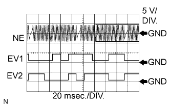
NE+ (E8-32) - NE- (E8-31)
| R - G
| Crankshaft position sensor
| Idling
| Pulse generation (see waveform 5, 6)
|
EV1+ (E6-19) - EV1- (E6-18)
| B - W
| Variable valve timing (VVT) sensor (Exhaust side (bank 1))
| Idling
| Pulse generation (see waveform 6)
|
EV2+ (E45-13) - EV2- (E45-12)
| G - R
| Variable valve timing (VVT) sensor (Exhaust side (bank 2))
| Idling
| Pulse generation (see waveform 6)
|
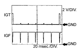
IGT1 (E6-13) - E1 (E7-7)
IGT2 (E8-17) - E1 (E7-7)
IGT3 (E6-10) - E1 (E7-7)
IGT4 (E6-12) - E1 (E7-7)
IGT5 (E8-27) - E1 (E7-7)
IGT6 (E8-26) - E1 (E7-7)
| L-R - BR
L-B - BR
V - BR
P-L - BR
W-L - BR
W-L - BR
| Ignition coil (ignition signal)
| Idling
| Pulse generation (see waveform 7)
|
IGF1 (E6-7) - E1 (E7-7)
IGF2 (E6-6) - E1 (E7-7)
| G - BR
G-B - BR
| Ignition coil (ignition confirmation signal)
| Engine switch on (IG)
| 4.5 to 5.0 V
|
IGF1 (E6-7) - E1 (E7-7)
IGF2 (E6-6) - E1 (E7-7)
| G - BR
G-B - BR
| Ignition coil (ignition confirmation signal)
| Idling
| Pulse generation (see waveform 7)
|
PRG (E8-11) - E1 (E7-7)
| W - BR
| VSV for EVAP
| Engine switch on (IG)
| 9 to 14 V
|
PRG (E8-11) - E1 (E7-7)
| W - BR
| VSV for EVAP
| Idling
| Pulse generation (see waveform 8)
|
SPD (A6-22) - E1 (E7-7)
| V-W - BR
| Speed signal from combination meter
| Engine switch on (IG), Rotate driving wheel slowly
| Pulse generation (see waveform 9)
|
STA (A6-12) - E1 (E7-7)
| R - BR
| Starter signal
| Cranking
| 9 to 14 V
|
STAR (E7-4) - E1 (E7-7)
| L-Y - BR
| Park/neutral position switch signal
| Engine switch on (IG), Other shift position in P or N
| 9 to 14 V
|
STAR (E7-4) - E1 (E7-7)
| L-Y - BR
| Park/neutral position switch signal
| Cranking, Shift position in P or N
| 0 to 3.0 V
|
STSW (A6-19) - E1 (E7-7)
| Y-B - BR
| Engine switch signal
| Shift lever position P or N, engine switch START
| 6.0 V or more
|
STP (A7-4) - E1 (E7-7)
| R-B - BR
| Stop light switch
| Brake pedal depressed
| 7.5 to 14 V
|
STP (A7-4) - E1 (E7-7)
| R-B - BR
| Stop light switch
| Brake pedal released
| Below 1.5 V
|
ST1- (A6-8) - E1 (E7-7)
| G-W - BR
| Stop light switch
(opposite to STP terminal)
| Engine switch on (IG), Brake pedal depressed
| Below 1.5 V
|
ST1- (A6-8) - E1 (E7-7)
| G-W - BR
| Stop light switch
(opposite and STP terminal)
| Engine switch on (IG), Brake pedal released
| 7.5 to 14 V
|
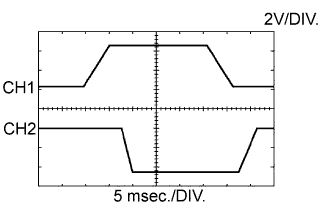
M+ (E8-2) - ME01 (E8-4)
| B - W-B
| Throttle actuator
| Idling with warm engine
| Pulse generation (see waveform 10)
|
M- (E8-1) - ME01 (E8-4)
| W - W-B
| Throttle actuator
| Idling with warm engine
| Pulse generation (see waveform 11)
|
FC (A6-14) - E1 (E7-7)
| R-G - BR
| Fuel pump control
| Engine switch on (IG)
| 9 to 14 V
|
FC (A6-14) - E1 (E7-7)
| R-G - BR
| Fuel pump control
| Idling
| 0 to 3 V
|
FPR (A6-15) - E1 (E7-7)
| R-W - BR
| Fuel pump control
| Cranking
| 9 to 14 V
|
FPR (A6-15) - E1 (E7-7)
| R-W - BR
| Fuel pump control
| Idling
| 9 to 14 V
|
W (A7-8) - E1 (E7-7)
| R-L - BR
| MIL
| Engine switch on (IG)
| Below 3.0 V
|
W (A7-8) - E1 (E7-7)
| R-L - BR
| MIL
| Idling
| 0 to 3 V
|
TC (A7-3) - E1 (E7-7)
| V - BR
| Terminal TC of DLC 3
| Engine switch on (IG)
| 9 to 14 V
|
TACH (A7-16) - E1 (E7-7)
| W-L - BR
| Engine speed
| Idling
| Pulse generation (see waveform 12)
|
ACIS (E6-3) - E1 (E7-7)
| Y - BR
| Intake air control valve actuator
| Engine switch on (IG)
| 9 to 14 V
|
ACIS (E6-3) - E1 (E7-7)
| Y - BR
| Intake air control valve actuator
| Engine RPM is 2,400 to 4,000 rpm and throttle opening percentage is 40 % or more
| 0 to 3 V
|
INJF (E45-26) - E1 (E7-7)
| GR - BR
| Injector injection confirmation signal
| Idling
| Pulse generation (see waveform 13)
|
FPF1 (E45-32) - E1 (E7-7)
| W-L - BR
| High pressure side fuel pump (spill valve)
| Idling
| Pulse generation (see waveform 14)
|
FPD (E45-33) - E1 (E7-7)
| R-L - BR
| High pressure side fuel pump (spill valve)
| Idling
| Pulse generation (see waveform 14)
|
PR (E45-25) - E2 (E8-28)
| L-B - BR
| Fuel pressure sensor
| Idling
| 1.8 to 2.3 V
|
IAC1 (E45-31) - E1 (E7-7)
| G - BR
| SCV position sensor
| Engine switch off to on (IG)
| 3.0 to 4.0 V
|
IA1+ (E45-2) - E01 (E6-2)
| LG-B - W-B
| DC motor for SCV
| Idling
| Pulse generation (see waveform 15)
|
IA1- (E45-1) - E01 (E6-2)
| Y-G - W-B
| DC motor for SCV
| Idling
| Pulse generation (see waveform 16)
|
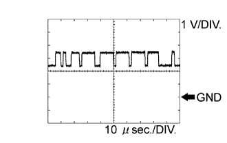
CANH (A6-25) - E1 (E7-7)
| B - BR
| CAN communication line
| Engine switch on (IG)
| Pulse generation (see waveform 17)
|
CANL (A6-24) - E1 (E7-7)
| W - BR
| CAN communication line
| Engine switch on (IG)
| Pulse generation (see waveform 18)
|