Automatic Transmission Unit -- Inspection |
| 1. INSPECT 1ST AND REVERSE BRAKE RETURN SPRING SUB-ASSEMBLY |
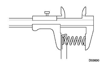
Using vernier calipers, measure the free length of the spring together with the spring seat.
- Standard free length:
- 23.74 mm (0.935 in.)
 |
| 2. INSPECT REAR PLANETARY GEAR ASSEMBLY |
Using a feeler gauge, measure the rear planetary gear pinion thrust clearance.
- Standard clearance:
- 0.2 to 0.6 mm (0.008 to 0.024 in.)
 |
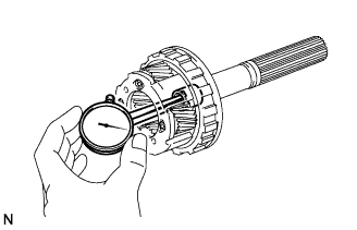
Using a dial indicator, measure the inside diameter of the rear planetary gear bushing.
- Standard inside diameter:
- 18.025 mm (0.710 in.)
 |
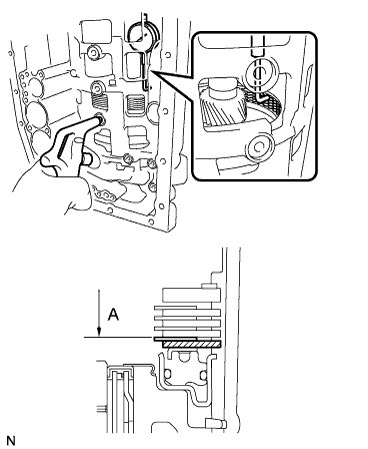
| 3. INSPECT PACK CLEARANCE OF 1ST AND REVERSE BRAKE |
Make sure that the 1st and reverse brake piston moves smoothly while applying compressed air intermittently into the transmission case.
 |
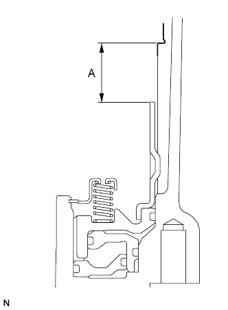
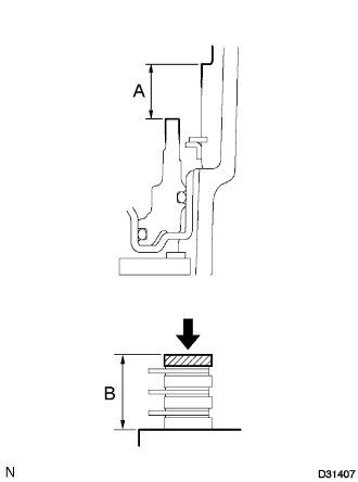
Using vernier calipers, measure the level difference (length A) between the upper surface of the brake apply tube and the hitting surface of the brake flange No.4 at both ends across the 1st and reverse brake piston diameter, and calculate the average.
- NOTICE:
- The 1st and reverse brake piston must be securely installed to the end face of the transmission case.
- HINT:
- Length A = 23.32 to 24.18 mm (0.9181 to 0.952 in.)
 |
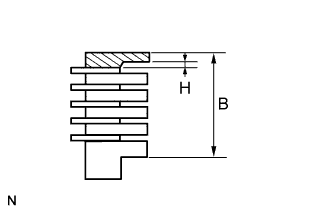
Using vernier calipers, measure the combined thickness (length B) of the brake flanges, the 4 brake plates No.4 and the 5 brake discs No.4 at both ends across the diameter, and calculate the average.
- HINT:
- Length B = 23.64 to 26.00 mm (0.9303 to 1.0236 in.)
- Pack Clearance = Length A - Length B - 0.18 mm (0.0071 in.) + 1.8 mm (0.071 in.)
- Pack Clearance:
- 0.5 to 0.8 mm (0.0197 to 0.0315 in.)
 |
If the pack clearance is outside the standard, select and install a brake flange that brings the pack clearance to be within the standard.
- HINT:
- There are 8 types of flanges that can be used to adjust the pack clearance. Select the one with the most appropriate thickness.
- Thickness H:
NO. Thickness H NO. Thickness H 0 0 mm (0 in.) 8 0.8 mm (0.03150 in.) 2 0.2 mm (0.00787 in.) 10 1.0 mm (0.03937 in.) 4 0.4 mm (0.01575 in.) 12 1.2 mm (0.04724 in.) 6 0.6 mm (0.02362 in.) 14 1.4 mm (0.05512 in.)
| 4. INSPECT BRAKE DISC NO.4 |
Check whether the sliding surfaces of the discs, the plates, and the flanges are worn or burnt.
If necessary, replace them.- NOTICE:
- If the linings of the discs are peeled off or discolored, or if any part of the printed numbers is damaged, replace all discs.
- Before assembling new discs, soak them in ATF for at least 15 minutes.
 |
| 5. INSPECT INTERMEDIATE SHAFT |
Using a dial indicator, check the intermediate shaft runout.
- Standard runout:
- 0.03mm (0.0012 in.)
 |
Using a micrometer, check the outer diameter of the intermediate shaft at each point shown in the illustration.
- Standard diameter:
- A:
- 22.962 to 22.975 mm (0.904 to 0.905 in.)
- B:
- 22.962 to 22.975 mm (0.904 to 0.905 in.)
- C:
- 27.759 to 27.775 mm (1.0929 to 1.0935 in.)
- D:
- 27.759 to 27.775 mm (1.0929 to 1.0935 in.)
 |
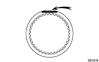
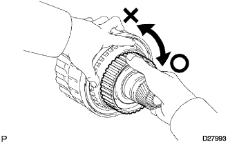
| 6. INSPECT 1 WAY NO.3 CLUTCH ASSEMBLY |
Hold the rear planetary ring gear flange sub-assembly and turn the 1 way clutch assembly.
 |
Check that the 1 way clutch assembly turns freely counterclockwise and locks clockwise.
If there is a problem with the 1 way clutch, replace it.
| 7. INSPECT CENTER PLANETARY GEAR ASSEMBLY |
Using a feeler gauge, measure the center planetary gear pinion thrust clearance.
- Standard clearance:
- 0.12 to 0.68 mm (0.005 to 0.027 in.)
 |
| 8. INSPECT BRAKE DISC NO.2 |
Check whether the sliding surfaces of the discs, the plates, and the flange are worn or burnt.
If necessary, replace them.- NOTICE:
- If the linings of the discs are peeled off or discolored, or if any part of the printed numbers is damaged, replace all discs.
- Before assembling new discs, soak them in ATF for at least 15 minutes.
|
| 9. INSPECT BRAKE PISTON RETURN SPRING SUB-ASSEMBLY NO.2 |
Using vernier calipers, measure the free length of the spring together with the spring seat.
- Standard free length:
- 22.66 mm (0.8921 in.)
 |
| 10. INSPECT PISTON STROKE OF BRAKE PISTON NO.2 |
Inspect the piston stroke of the brake piston No.2.
Make sure that the brake piston No.2 moves smoothly while applying compressed air intermittently into the transmission case.
Using SST and a dial indicator, measure the moving distance (distance A) of the clutch disc at both ends across the diameter while blowing air from the oil hole as shown in the illustration, and calculate the average.
- SST
- 09350-30020(09350-06120)
- Pack Clearance:
- 0.6 to 0.9 mm (0.024 to 0.035 in.)
If the piston stroke is outside the standard, select and install a brake flange that brings the piston stroke within the standard.
- HINT:
- There are 8 types of flanges that can be used to adjust the pack clearance. Select one with the most appropriate thickness.
- Flange thickness:
No. Thickness 0 2.0 mm (0.079 in.) 1 2.1 mm (0.083 in.) 2 2.2 mm (0.087 in.) 3 2.3 mm (0.091 in.) 4 2.4 mm (0.094 in.) 5 2.5 mm (0.098 in.) 6 2.6 mm (0.102 in.) 7 2.7 mm (0.106 in.)

| 11. INSPECT BRAKE PISTON RETURN SPRING SUB-ASSEMBLY |
Using vernier calipers, measure the free length of the spring together with the spring seat.
- Standard free length:
- 17.05 mm (0.671 in.)
 |
| 12. INSPECT FRONT PLANETARY GEAR ASSEMBLY |
Using a feeler gauge, measure the front planetary pinion gear thrust clearance.
- Standard clearance:
- 0.20 to 0.60 mm (0.008 to 0.024 in.)
 |
Using a dial indicator, measure the inside diameter of the front planetary gear bushing.
- Standard inside diameter:
- 48.78 mm (1.9205 in.)
 |
| 13. INSPECT 1 WAY CLUTCH ASSEMBLY |
Install the 1 way clutch assembly to the 1 way clutch inner race.
 |
Hold the 1 way clutch inner race and turn the 1 way clutch assembly.
Check that the 1 way clutch assembly turns freely counterclockwise and locks clockwise.
If there is a problem with the 1 way clutch, replace it.
Remove the 1 way clutch assembly from the 1 way clutch inner race.
| 14. INSPECT PISTON STROKE OF BRAKE PISTON NO.1 |
Inspect the piston stroke of brake piston No.1.
Make sure the brake piston No.1 moves smoothly while applying compressed air intermittently into the transmission case.
Using vernier calipers, measure the level difference (length A) between the upper surface of the brake piston No.1 and the hitting surface of the brake flange No.1 at both ends across the brake piston No.1 diameter.
Using vernier calipers, measure the thickness (length B) of the brake flange, the 3 brake plates No.1 and the 3 brake discs No.1 altogether at both ends across the diameter, and calculate the average.
- HINT:
- Length A = 15.27 to 15.92 mm (0.60118 to 0.62677 in.)
- Length B = 14.50 to 15.54 mm (0.57087 to 0.691181 in.)
- Piston stroke = Length A - Length B
- Piston stroke:
- 0.42 to 0.72 mm (0.017 to 0.028 in.)
If the piston stroke not still outside the specification range, select another flange that brings the piston stroke within the specification.- HINT:
- There are 4 different thicknesses for the flange.
- Flange thickness:
No. Thickness 0 2.0 mm (0.079 in.) 1 2.2 mm (0.087 in.) 2 2.4 mm (0.094 in.) 3 2.6 mm (0.102 in.)

| 15. INSPECT BRAKE DISC NO.1 |
Check whether the sliding surfaces of the discs, the plates, or the flange are worn or burnt.
If necessary, replace them.- NOTICE:
- If the linings of the discs are peeled off or discolored, or if any part of the groove is damaged, replace all discs.
- Before assembling new discs, soak them in ATF for at least 15 minutes.
|
| 16. INSPECT 2ND BRAKE DISC SET |
Check whether the sliding surfaces of the discs, the plates, or the flange are worn or burnt.
If necessary, replace them.- NOTICE:
- If the linings of the discs are peeled off or discolored, or if any part of the printed numbers is damaged, replace all discs.
- Before assembling new discs, soak them in ATF for at least 15 minutes.
|
| 17. INSPECT 1 WAY NO.2 CLUTCH ASSEMBLY |
Hold the reverse clutch hub and turn the 1 way No.2 clutch assembly.
 |
Check that the 1 way No.2 clutch assembly turns freely clockwise and locks counterclockwise.
If there is a problem with the 1 way clutch, replace it.
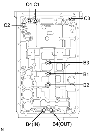
| 18. INSPECT INDIVIDUAL PISTON OPERATION |
Check the operating sound while applying compressed air into the oil holes indicated in the illustration.
- HINT:
- When inspecting the O/D direct clutch, check with the C3 accumulator piston hole closed.
- If there is no sound, disassemble and check the parts installation condition.
Clutch No.2 (C2)
Clutch No.4 (C4)
Clutch No.3 (C3)
Clutch No.1 (C1)
Brake No.3 (B3)
Brake No.1 (B1)
Brake No.2 (B2)
Brake No.4 (B4)
 |