Automatic Transmission Assembly Installation
INSPECT TORQUE CONVERTER CLUTCH ASSEMBLY
INSTALL TORQUE CONVERTER CLUTCH ASSEMBLY
INSTALL TRANSMISSION CONTROL SHAFT LEVER RH
INSTALL ENGINE MOUNTING INSULATOR REAR NO.1
INSTALL AUTOMATIC TRANSMISSION ASSEMBLY
INSTALL FLYWHEEL HOUSING UNDER COVER
INSTALL WIRE HARNESS AND CONNECTORS
INSTALL ENGINE REAR MOUNTING MEMBER
CONNECT FLOOR SHIFT GEAR SHIFTING ROD SUB-ASSEMBLY
INSTALL OIL COOLER OUTLET TUBE NO.1
INSTALL OIL COOLER INLET TUBE NO.1
ADJUST SHIFT LEVER POSITION
INSPECT SHIFT LEVER POSITION
INSTALL PROPELLER W/CENTER BEARING SHAFT ASSEMBLY
INSTALL EXHAUST PIPE NO.1 SUPPORT BRACKET SUB-ASSEMBLY
INSTALL FRONT EXHAUST PIPE ASSEMBLY
INSTALL ENGINE UNDER COVER AIR GUIDE BRACKET
ADD AUTOMATIC TRANSMISSION FLUID
INSTALL ENGINE UNDER COVER NO.2
INSTALL ENGINE UNDER COVER
RESET MEMORY
PERFORM INITIALIZATION
Automatic Transmission Assembly -- Installation |
| 1. INSPECT TORQUE CONVERTER CLUTCH ASSEMBLY |
(Click here)
| 2. INSTALL TORQUE CONVERTER CLUTCH ASSEMBLY |
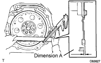
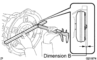
Using calipers and a straight edge, measure dimension A between the transmission and the end surface of the drive plate.
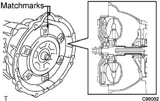
Aligning the matchmarks on the transmission case and torque converter clutch, engage the splines of the input shaft and turbine runner.
Engage the splines of the stator shaft and stator while turning the torque converter clutch.
- HINT:
- Turn the torque converter clutch approximately 180°.
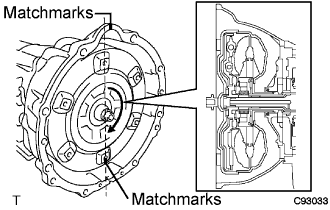
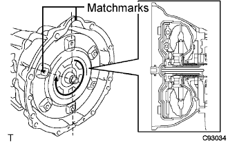
Turn the torque converter clutch and align the matchmarks on the torque converter clutch and transmission case to engage the key of the oil pump drive gear into the slot on the torque converter clutch.
- NOTICE:
- Do not push on the torque converter when aligning the matchmarks.
Using calipers and a straight edge, measure dimension B shown in the illustration and check that B is greater than A measured in step (a).
- Standard:
- A + 1 mm or more
| 3. INSTALL TRANSMISSION CONTROL SHAFT LEVER RH |
Install the transmission control shaft lever RH with the nut.
- Torque:
- 16 N*m{160 kgf*cm, 12 ft.*lbf}
| 4. INSTALL ENGINE MOUNTING INSULATOR REAR NO.1 |
Install the engine mounting insulator rear No.1 with the 4 bolts.
- Torque:
- 12 N*m{122 kgf*cm, 9 ft.*lbf}
| 5. INSTALL AUTOMATIC TRANSMISSION ASSEMBLY |
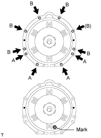
Install the automatic transmission assembly to the engine with the 9 bolts.
- Torque:
- Bolt A: 14 mm head bolt:
- 37 N*m{377 kgf*cm, 27 ft.*lbf}
- Bolt B: 17 mm head bolt:
- 71 N*m{724 kgf*cm, 52 ft.*lbf}
- HINT:
- Make sure that the mark is position as shown in the illustration.
- Bolt (B) will be tightened with the wire harness clamp.
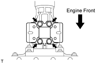
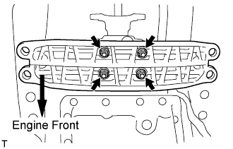
Install the 6 torque converter clutch mounting bolts.
- Torque:
- 48 N*m{489 kgf*cm, 35 ft.*lbf}
- HINT:
- First install the black colored bolt and then the remaining 5 bolts.
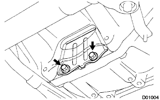
| 6. INSTALL FLYWHEEL HOUSING UNDER COVER |
Install the fly wheel housing under cover with the 2 bolts.
- Torque:
- 18 N*m{184 kgf*cm, 13 ft.*lbf}
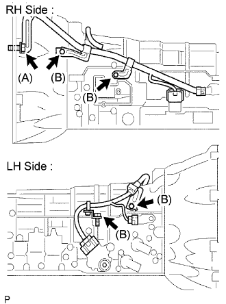
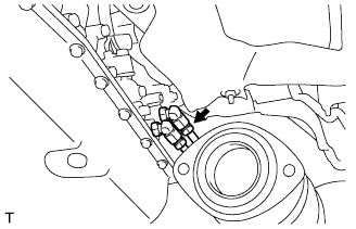
| 7. INSTALL WIRE HARNESS AND CONNECTORS |
Connect the 2 speed sensor connectors.
Connect the transmission wire connector.
Connect the park/neutral position switch connector.
Install the wire harness clamps with the 5 bolts.
- Torque:
- Bolt (A):
- 71 N*m{724 kgf*cm, 52 ft.*lbf}
- Bolt (B):
- 10 N*m{102 kgf*cm, 7 ft.*lbf}
- HINT:
- Bolt (A) is tightened to the transmission housing.
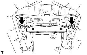
| 8. INSTALL ENGINE REAR MOUNTING MEMBER |
Install the engine rear mounting member with the 4 nuts.
- Torque:
- 13 N*m{133 kgf*cm, 10 ft.*lbf}
Install the engine rear mounting member with the 4 bolts.
- Torque:
- 26 N*m{265 kgf*cm, 19 ft.*lbf}
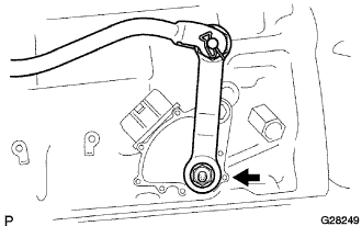
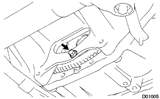
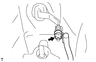
| 9. CONNECT FLOOR SHIFT GEAR SHIFTING ROD SUB-ASSEMBLY |
Connect the floor shift gear shifting rod sub-assembly with the nut.
- Torque:
- 13 N*m{130 kgf*cm, 9 ft.*lbf}
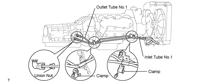
| 10. INSTALL OIL COOLER OUTLET TUBE NO.1 |
Temporarily install the oil cooler outlet tube No.1.
Temporarily install the oil cooler inlet tube No.1.
Install the 2 clamps with the 2 bolts.
- Torque:
- 5.0 N*m{51 kgf*cm, 44 in.*lbf}
Tighten the oil cooler outlet tube No.1.
- Torque:
- 42 N*m{428 kgf*cm, 31 ft.*lbf}
- NOTICE:
- Use a torque wrench with a fulcrum length of 460 mm (18.11 in.)
| 11. INSTALL OIL COOLER INLET TUBE NO.1 |
Tighten the oil cooler inlet tube No.1.
- Torque:
- 42 N*m{428 kgf*cm, 31 ft.*lbf}
- NOTICE:
- Use a torque wrench with a fulcrum length of 460 mm (18.11 in.)
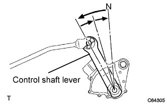
| 12. ADJUST SHIFT LEVER POSITION |
Remove the nut and disconnect the shifting rod.
Turn the control shaft lever of the neutral start switch counterclockwise until it stops, and turn it clockwise 2 notches to set it to the N position.
Move the shift lever to the N position and tighten the nut while lightly pushing the lever toward the R position.
- NOTICE:
- Do not push the shift lever too hard.
After adjustment, check that the shift lever moves smoothly and the shift lever and gear operate correctly.
| 13. INSPECT SHIFT LEVER POSITION |
When shifting from the P to the R position with the engine switch on (IG) and brake pedal depressed, make sure that the shift lever moves smoothly and moves correctly into position.
Start the engine and make sure that the vehicle moves forward when shifting from the N to the D position and moves rearward when shifting to the R position.
If operation cannot be done as specified, inspect the park/neutral position switch assembly and check the shift lever assembly installation condition.
| 14. INSTALL PROPELLER W/CENTER BEARING SHAFT ASSEMBLY |
(Click here)
| 15. INSTALL EXHAUST PIPE NO.1 SUPPORT BRACKET SUB-ASSEMBLY |
Install the exhaust pipe No.1 support bracket sub-assembly with the 2 bolts.
- Torque:
- 43 N*m{438 kgf*cm, 32 ft.*lbf}
| 16. INSTALL FRONT EXHAUST PIPE ASSEMBLY |
(Click here)
| 17. INSTALL ENGINE UNDER COVER AIR GUIDE BRACKET |
Install the engine under cover air guide bracket with the 2 bolts.
- Torque:
- 26 N*m{260 kgf*cm, 19 ft.*lbf}
| 18. ADD AUTOMATIC TRANSMISSION FLUID |
(Click here)
| 19. INSTALL ENGINE UNDER COVER NO.2 |
| 20. INSTALL ENGINE UNDER COVER |
(Click here)
| 22. PERFORM INITIALIZATION |
(Click here)