Rear Axle Hub -- Removal |
| 1. REMOVE REAR WHEEL |
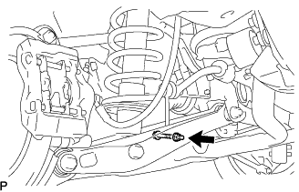
| 2. SEPARATE REAR STABILIZER LINK ASSEMBLY |
Remove the bolt and nut, and separate the stabilizer link assembly and load sensing valve sensor bracket.
 |
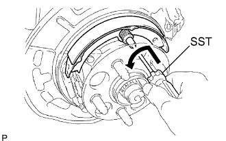
| 3. REMOVE REAR AXLE SHAFT NUT |
Using SST and a hammer, release the staked part of the axle shaft nut.
- SST
- 09930-00010
- NOTICE:
- Release the staked part of the nut completely, otherwise the screw of the drive shaft may be damaged.
 |
While applying the brakes, remove the rear axle shaft nut.
| 4. SEPARATE REAR DISC BRAKE CALIPER ASSEMBLY |
Remove the 2 bolts, and disconnect the rear disc brake caliper assembly.
- NOTICE:
- Use a wire or an equivalent to keep the brake caliper from hanging down by the flexible hose.
 |
Remove the caliper plates No.1 from the brake caliper.
| 5. REMOVE REAR DISC |
| 6. SEPARATE SPEED SENSOR REAR |
Remove the 2 bolts, and separate the speed sensor from the axle carrier.
- NOTICE:
- Be careful not to damage the speed sensor.
- Prevent foreign matter from adhering to the speed sensor.
 |
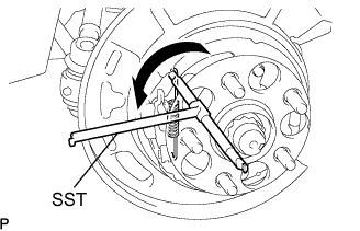
| 7. REMOVE PARKING BRAKE SHOE RETURN SPRING NO.2 |
Using SST, remove the parking brake shoe return No.2 spring.
- SST
- 09703-30011
 |
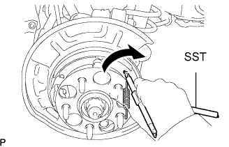
| 8. REMOVE PARKING BRAKE SHOE RETURN SPRING NO.1 |
Using SST, remove the parking brake shoe return No.1 spring.
- SST
- 09703-30011
 |
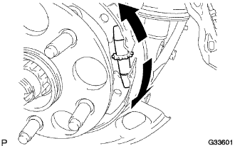
| 9. REMOVE PARKING BRAKE SHOE ADJUSTING SCREW SET |
Slide the parking brake shoe, and remove the parking brake shoe adjusting screw set.
 |
| 10. REMOVE PARKING BRAKE SHOE ASSEMBLY NO.1 |
Using SST, remove the shoe hold down spring No.1 cup, compression No.1 spring and shoe hold down spring No.1 pin.
- SST
- 09718-00010
 |
Remove the parking brake No.1 shoe assembly.
| 11. REMOVE PARKING BRAKE SHOE ASSEMBLY NO.2 |
Using SST, remove the shoe hold down spring No.1 cup, compression No.1 spring and shoe hold down spring No.1 pin.
- SST
- 09718-00010
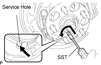 |
Remove the parking brake No.2 shoe assembly.
- HINT:
- Use the service hole to retain the hold down spring No.1 pin with your finger.
| 12. INSTALL PARKING BRAKE SHOE LEVER |
| 13. REMOVE PARKING BRAKE ANCHOR BLOCK |
Remove the 2 nuts and the parking brake anchor block sub-assembly from the rear axle carrier sub-assembly.
 |
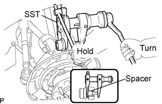
| 14. SEPARATE UPPER CONTROL ARM ASSEMBLY REAR NO.2 |
Remove the nut from the upper control arm assembly rear No.2.
Using SST, separate the upper control arm assembly rear No.2 from the rear axle carrier sub-assembly.
- SST
- 09628-00011
- NOTICE:
- Pay careful attention not to damage the rear axle carrier because it is made of aluminum and may be damaged easily.
- Do not damage the ball joint dust cover.
- Make sure that the SST is securely set to the rear axle carrier spacer.
- If the rear axle carrier spacer has come off, replace the rear axle carrier with a new one.
- Make sure that the string of the SST is securely tied to the vehicle.
 |
| 15. SEPARATE UPPER CONTROL ARM ASSEMBLY REAR NO.1 |
Jack up the rear axle assembly so that the bolt on the upper control arm assembly rear No.1 can be removed.
- HINT:
- Place a wooden block between the jack and rear axle carrier to prevent damage to the rear axle carrier.
Remove the bolt, washer and nut, and separate the upper control arm assembly rear No.1 from the rear axle carrier sub-assembly.
 |
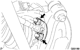
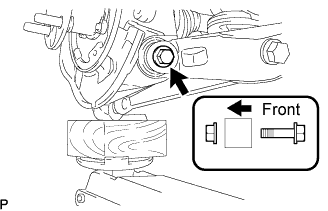
| 16. SEPARATE REAR SUSPENSION ARM ASSEMBLY NO.1 |
Remove the bolt and nut, and separate the rear suspension arm assembly No.1 from the rear axle carrier sub-assembly.
- NOTICE:
- Turn the bolt while holding the nut.
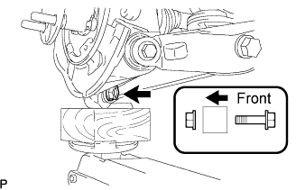 |
| 17. SEPARATE REAR SUSPENSION ARM ASSEMBLY NO.2 |
Remove the bolt and nut, and separate the rear suspension arm assembly No.2 from the rear axle carrier sub-assembly.
- NOTICE:
- Turn the bolt while holding the nut.
 |
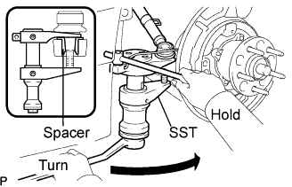
| 18. SEPARATE TOE CONTROL LINK SUB-ASSEMBLY |
Remove the nut from the toe control link sub-assembly.
Using SST, separate the toe control link sub-assembly from the rear axle carrier sub-assembly.
- SST
- 09628-00011
- NOTICE:
- Pay careful attention not to damage the rear axle carrier because it is made of aluminum and may be damaged easily.
- Do not damage the ball joint dust cover.
- Make sure that the SST is securely set to the rear axle carrier spacer.
- If the rear axle carrier spacer has come off, replace the rear axle carrier with a new one.
- Make sure that the string of the SST is securely tied to the vehicle.
 |
| 19. REMOVE REAR AXLE ASSEMBLY |
Using a plastic hammer, separate the drive shaft from the rear axle carrier sub-assembly.
Remove the rear axle assembly.
- NOTICE:
- Be careful not to damage the boot.
- Use a wire or an equivalent to keep the rear drive shaft assembly from hanging down.
| 20. REMOVE REAR WHEEL BEARING DUST DEFLECTOR NO.2 |
Using a screwdriver, remove the bearing dust deflector No.2 from the rear axle carrier sub-assembly.
 |
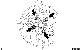
| 21. REMOVE REAR AXLE HUB AND BEARING ASSEMBLY |
Hold the axle hub and bearing assembly in a vise between aluminium plates.
- NOTICE:
- Do not overtighten the vise.
Remove the 4 bolts and axle hub and bearing assembly from the rear axle carrier sub-assembly.
 |