DESCRIPTION
WIRING DIAGRAM
INSPECTION PROCEDURE
CHECK STEREO COMPONENT AMPLIFIER
CHECK SPEAKER
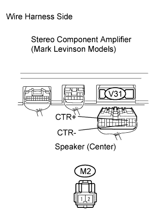
INSPECT SPEAKER (CENTER)
CHECK WIRE HARNESS (STEREO COMPONENT AMPLIFIER - SPEAKER (CENTER))
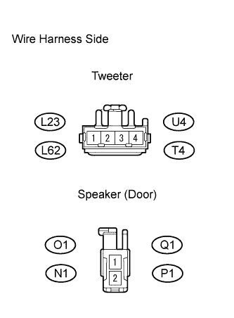
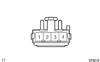
INSPECT TWEETER
CHECK WIRE HARNESS (STEREO COMPONENT AMPLIFIER - TWEETER)
INSPECT SPEAKER (DOOR)
CHECK WIRE HARNESS (TWEETER - SPEAKER DOOR)
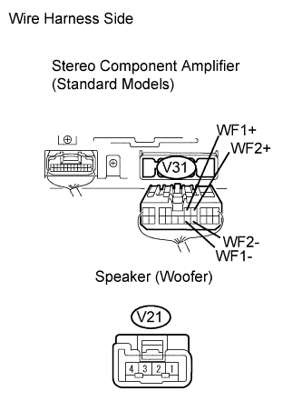
INSPECT SPEAKER (WOOFER)
CHECK WIRE HARNESS (STEREO COMPONENT AMPLIFIER - SPEAKER WOOFER)
CHECK SPEAKER
CHECK SPEAKER
INSPECT SPEAKER (CENTER)
CHECK WIRE HARNESS (STEREO COMPONENT AMPLIFIER - SPEAKER (CENTER))
INSPECT SQUAWKER AND TWEETER
CHECK WIRE HARNESS (STEREO COMPONENT AMPLIFIER - SQUAWKER AND TWEETER)
INSPECT SPEAKER (FRONT DOOR)
CHECK WIRE HARNESS (STEREO COMPONENT AMPLIFIER - SPEAKER (FRONT DOOR))
CHECK SPEAKER
INSPECT TWEETER (REAR)
CHECK WIRE HARNESS (STEREO COMPONENT AMPLIFIER - TWEETER (REAR))
INSPECT SPEAKER (REAR DOOR)
CHECK WIRE HARNESS (TWEETER (REAR) - SPEAKER (REAR DOOR))
INSPECT SPEAKER (REAR)
CHECK WIRE HARNESS (STEREO COMPONENT AMPLIFIER - SPEAKER (REAR))
INSPECT SPEAKER (WOOFER)
CHECK WIRE HARNESS (STEREO COMPONENT AMPLIFIER - SPEAKER WOOFER)
AUDIO AND VISUAL SYSTEM - Speaker Circuit |
DESCRIPTION
The stereo component amplifier sends sound signals to the speaker.
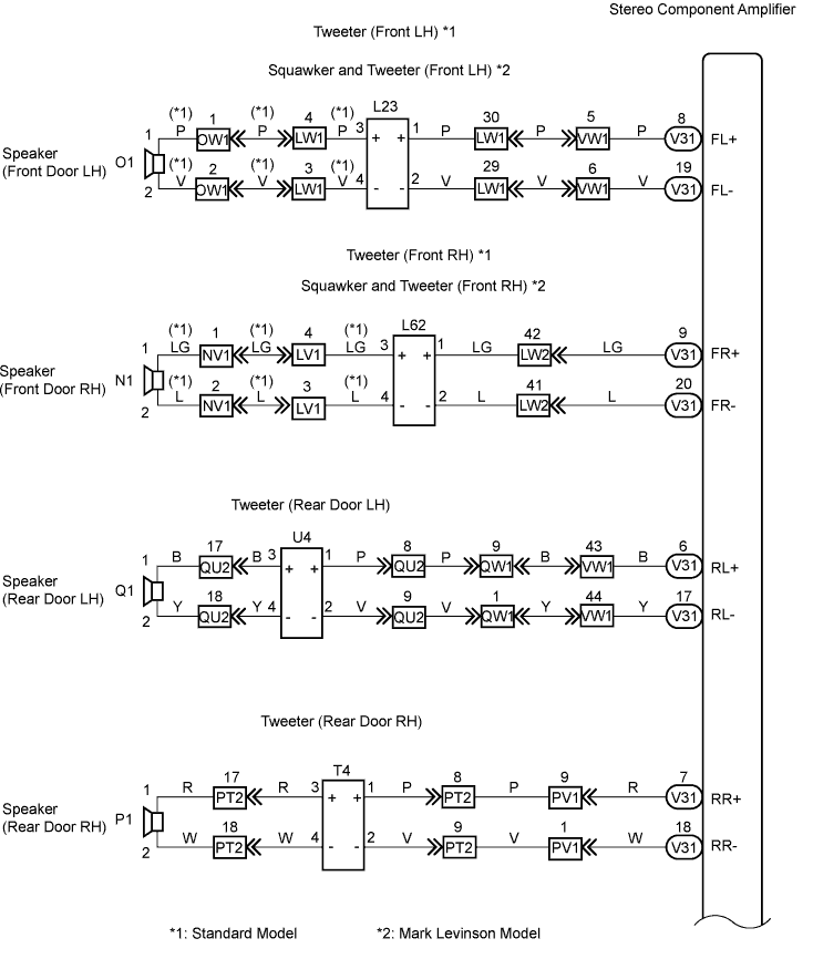
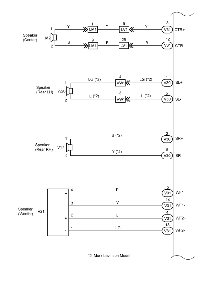
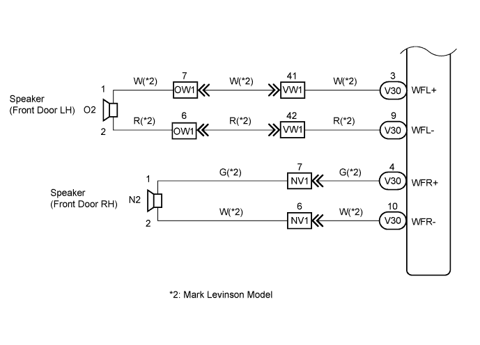
WIRING DIAGRAM
INSPECTION PROCEDURE
| 1.CHECK STEREO COMPONENT AMPLIFIER |
Check stereo component amplifier model.
- Result:
Model
| Proceed to
|
Standard model
| A
|
Mark Levinson model
| B
|
Check the malfunctioning speakers.
- Result:
Result
| Proceed to
|
Speaker (Center)
| A
|
Tweeter
| B
|
Speaker (Door)
| C
|
Speaker (Woofer)
| D
|
| 3.INSPECT SPEAKER (CENTER) |
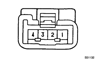
Disconnect the M2 speaker (center) connector.
Measure the resistance of the connector.
- Standard resistance:
Tester Connection
| Specified Condition
|
1 - 2
| Approx. 10 Ω
|
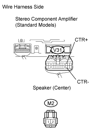
| 4.CHECK WIRE HARNESS (STEREO COMPONENT AMPLIFIER - SPEAKER (CENTER)) |
Disconnect the M2 speaker (center) connector.
Disconnect the V31 stereo component amplifier connector.
Measure the resistance of the wire harness side connectors.
- Standard resistance:
Tester Connection
| Specified Condition
|
V31-3 (CTR+) - M2-1
| Below 1 Ω
|
V31-12 (CTR-) - M2-2
| Below 1 Ω
|
V31-3 (CTR+) - Body ground
| 10 kΩ or higher
|
V31-12 (CTR-) - Body ground
| 10 kΩ or higher
|
| | REPAIR OR REPLACE HARNESS AND CONNECTOR |
|
|
| OK |
|
|
|
| REPLACE STEREO COMPONENT AMPLIFIER |
|
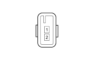
Disconnect the L23, L62, U4 and T4 tweeter connectors.
Measure the resistance of the connector.
- Standard resistance:
Tester Connection
| Specified Condition
|
1 - 2
| Approx. 4 Ω
|
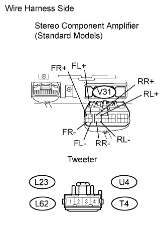
| 6.CHECK WIRE HARNESS (STEREO COMPONENT AMPLIFIER - TWEETER) |
Disconnect the V31 stereo component amplifier connector.
Disconnect the L23, L62, U4 and T4 tweeter connectors.
Measure the resistance of the wire harness side connectors.
- Standard resistance:
Tester Connection
| Specified Condition
|
V31-8 (FL+) - L23-1
| Below 1 Ω
|
V31-19 (FL-) - L23-2
| Below 1 Ω
|
V31-9 (FR+) - L62-1
| Below 1 Ω
|
V31-20 (FR-) - L62-2
| Below 1 Ω
|
V31-6 (RL+) - U4-1
| Below 1 Ω
|
V31-17 (RL-) - U4-2
| Below 1 Ω
|
V31-7 (RR+) - T4-1
| Below 1 Ω
|
V31-18 (RR-) - T4-2
| Below 1 Ω
|
V31-8 (FL+) - Body ground
| 10 kΩ or higher
|
V31-19 (FL-) - Body ground
| 10 kΩ or higher
|
V31-9 (FR+) - Body ground
| 10 kΩ or higher
|
V31-20 (FR-) - Body ground
| 10 kΩ or higher
|
V31-6 (RL+) - Body ground
| 10 kΩ or higher
|
V31-17 (RL-) - Body ground
| 10 kΩ or higher
|
V31-7 (RR+) - Body ground
| 10 kΩ or higher
|
V31-18 (RR-) - Body ground
| 10 kΩ or higher
|
| | REPAIR OR REPLACE HARNESS AND CONNECTOR |
|
|
| OK |
|
|
|
| REPLACE STEREO COMPONENT AMPLIFIER |
|
Disconnect the O1, N1, Q1 and P1 speaker (door) connectors.
Measure the resistance of the connector.
- Standard resistance:
Tester Connection
| Specified Condition
|
1 - 2
| Approx. 4 Ω
|
| 8.CHECK WIRE HARNESS (TWEETER - SPEAKER DOOR) |
Disconnect the L23, L62, U4 and T4 tweeter connectors.
Disconnect the O1, N1, Q1 and P1 speaker (door) connectors.
Measure the resistance of the wire harness side connectors.
- Standard resistance:
Tester Connection
| Specified Condition
|
L23-3 - O1-1
| Below 1 Ω
|
L23-4 - O1-2
| Below 1 Ω
|
L62-3 - N1-1
| Below 1 Ω
|
L62-4 - N1-2
| Below 1 Ω
|
U4-3 - P1-1
| Below 1 Ω
|
U4-4 - P1-2
| Below 1 Ω
|
T4-3 - Q1-1
| Below 1 Ω
|
T4-4 - Q1-2
| Below 1 Ω
|
| | REPAIR OR REPLACE HARNESS AND CONNECTOR |
|
|
| 9.INSPECT SPEAKER (WOOFER) |
Disconnect the V21 speaker (woofer) connector.
Measure the resistance of the connector.
- Standard resistance:
Tester Connection
| Specified Condition
|
1 - 2
| Approx. 2.5 Ω
|
3 - 4
|
| 10.CHECK WIRE HARNESS (STEREO COMPONENT AMPLIFIER - SPEAKER WOOFER) |
Disconnect the V31 stereo component amplifier connector.
Disconnect the V21 speaker (woofer) connector.
Measure the resistance of the wire harness side connectors.
- Standard resistance:
Tester Connection
| Specified Condition
|
V31-5 (WF1+) - V21-4
| Below 1 Ω
|
V31-14 (WF1-) - V21-3
| Below 1 Ω
|
V31-4 (WF2+) - V21-2
| Below 1 Ω
|
V31-13 (WF2-) - V21-1
| Below 1 Ω
|
V31-5 (WF1+) - Body ground
| 10 kΩ or higher
|
V31-14 (WF1-) - Body ground
| 10 kΩ or higher
|
V31-4 (WF2+) - Body ground
| 10 kΩ or higher
|
V31-13 (WF2-) - Body ground
| 10 kΩ or higher
|
| | REPAIR OR REPLACE HARNESS AND CONNECTOR |
|
|
| OK |
|
|
|
| REPLACE STEREO COMPONENT AMPLIFIER |
|
Check the malfunctioning speakers.
- Result:
Result
| Proceed to
|
Malfunction condition from the front speaker
| A
|
Malfunction condition from the rear speaker
| B
|
Check the malfunctioning speakers.
- Result:
Result
| Proceed to
|
Speaker (Center)
| A
|
Tweeter and squawker
| B
|
Speaker (Front door)
| C
|
| 13.INSPECT SPEAKER (CENTER) |
Disconnect the M2 speaker (center) connector.
Measure the resistance of the connector.
- Standard resistance:
Tester Connection
| Specified Condition
|
1 - 2
| Approx. 8 Ω
|
| 14.CHECK WIRE HARNESS (STEREO COMPONENT AMPLIFIER - SPEAKER (CENTER)) |
Disconnect the M2 speaker (center) connector.
Disconnect the V31 stereo component amplifier connector.
Measure the resistance of the wire harness side connectors.
- Standard resistance:
Tester Connection
| Specified Condition
|
V31-3 (CTR+) - M2-1
| Below 1 Ω
|
V31-12 (CTR-) - M2-2
| Below 1 Ω
|
V31-3 (CTR+) - Body ground
| 10 kΩ or higher
|
V31-12 (CTR-) - Body ground
| 10 kΩ or higher
|
| | REPAIR OR REPLACE HARNESS AND CONNECTOR |
|
|
| OK |
|
|
|
| REPLACE STEREO COMPONENT AMPLIFIER |
|
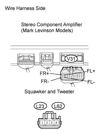
| 15.INSPECT SQUAWKER AND TWEETER |
Disconnect the L23 and L62 squawker and tweeter connectors.
Measure the resistance of the connector.
- Standard resistance:
Tester Connection
| Specified Condition
|
1 - 2
| Approx. 7 Ω
|
| | REPLACE SQUAWKER AND TWEETER |
|
|
| 16.CHECK WIRE HARNESS (STEREO COMPONENT AMPLIFIER - SQUAWKER AND TWEETER) |
Disconnect the V31 stereo component amplifier connector.
Disconnect the L23 and L62 squawker and tweeter connectors.
Measure the resistance of the wire harness side connectors.
- Standard resistance:
Tester Connection
| Specified Condition
|
V31-8 (FL+) - L23-1
| Below 1 Ω
|
V31-19 (FL-) - L23-2
| Below 1 Ω
|
V31-9 (FR+) - L62-1
| Below 1 Ω
|
V31-20 (FR-) - L62-2
| Below 1 Ω
|
V31-8 (FL+) - Body ground
| 10 kΩ or higher
|
V31-19 (FL-) - Body ground
| 10 kΩ or higher
|
V31-9 (FR+) - Body ground
| 10 kΩ or higher
|
V31-20 (FR-) - Body ground
| 10 kΩ or higher
|
| | REPAIR OR REPLACE HARNESS AND CONNECTOR |
|
|
| OK |
|
|
|
| REPLACE STEREO COMPONENT AMPLIFIER |
|
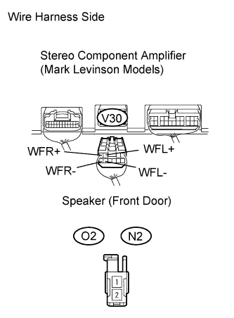
| 17.INSPECT SPEAKER (FRONT DOOR) |
Disconnect the O2 and N2 speaker (front door) connectors.
Measure the resistance of the connector.
- Standard resistance:
Tester Connection
| Specified Condition
|
1 - 2
| Approx. 8 Ω
|
| | REPLACE SPEAKER (FRONT DOOR) |
|
|
| 18.CHECK WIRE HARNESS (STEREO COMPONENT AMPLIFIER - SPEAKER (FRONT DOOR)) |
Disconnect the V30 stereo component amplifier connector.
Disconnect the O2 and N2 speaker (front door) connectors.
Measure the resistance of the wire harness side connectors.
- Standard resistance:
Tester Connection
| Specified Condition
|
V30-3 (WFL+) - O2-1
| Below 1 Ω
|
V30-9 (WFL1-) - O2-2
| Below 1 Ω
|
V30-4 (WFR+) - N2-1
| Below 1 Ω
|
V30-10 (WFR-) - N2-2
| Below 1 Ω
|
V30-3 (WFL+) - Body ground
| 10 kΩ or higher
|
V30-9 (WFL-) - Body ground
| 10 kΩ or higher
|
V30-4 (WFR+) - Body ground
| 10 kΩ or higher
|
V30-10 (WFR-) - Body ground
| 10 kΩ or higher
|
| | REPAIR OR REPLACE HARNESS AND CONNECTOR |
|
|
| OK |
|
|
|
| REPLACE STEREO COMPONENT AMPLIFIER |
|
Check the malfunctioning speakers.
- Result:
Result
| Proceed to
|
Tweeter (Rear)
| A
|
Speaker (Rear door)
| B
|
Speaker (Rear)
| C
|
Speaker (Woofer)
| D
|
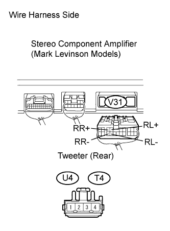
| 20.INSPECT TWEETER (REAR) |
Disconnect the U4 and T4 tweeter (rear) connectors.
Measure the resistance of the connector.
- Standard resistance:
Tester Connection
| Specified Condition
|
1 - 2
| Approx. 8 Ω
|
| 21.CHECK WIRE HARNESS (STEREO COMPONENT AMPLIFIER - TWEETER (REAR)) |
Disconnect the V31 stereo component amplifier connector.
Disconnect the U4 and T4 tweeter (rear) connectors.
Measure the resistance of the wire harness side connectors.
- Standard resistance:
Tester Connection
| Specified Condition
|
V31-6 (RL+) - U4-1
| Below 1 Ω
|
V31-17 (RL-) - U4-2
| Below 1 Ω
|
V31-7 (RR+) - T4-1
| Below 1 Ω
|
V31-18 (RR-) - T4-2
| Below 1 Ω
|
V31-6 (RL+) - Body ground
| 10 kΩ or higher
|
V31-17 (RL-) - Body ground
| 10 kΩ or higher
|
V31-7 (RR+) - Body ground
| 10 kΩ or higher
|
V31-18 (RR-) - Body ground
| 10 kΩ or higher
|
| | REPAIR OR REPLACE HARNESS AND CONNECTOR |
|
|
| OK |
|
|
|
| REPLACE STEREO COMPONENT AMPLIFIER |
|
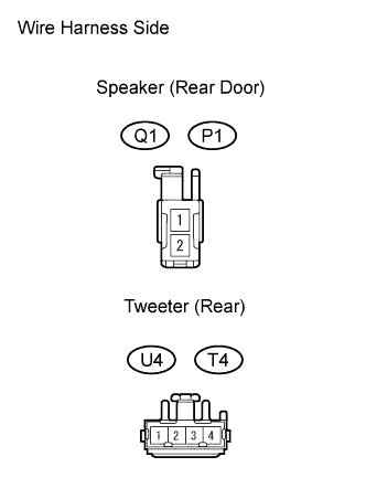
| 22.INSPECT SPEAKER (REAR DOOR) |
Disconnect the P1 and Q1 speaker (rear door) connectors.
Measure the resistance of the connector.
- Standard resistance:
Tester Connection
| Specified Condition
|
1 - 2
| Approx. 8 Ω
|
| | REPLACE SPEAKER (REAR DOOR) |
|
|
| 23.CHECK WIRE HARNESS (TWEETER (REAR) - SPEAKER (REAR DOOR)) |
Disconnect the Q1 and P1 speaker (rear door) connectors.
Disconnect the U4 and T4 tweeter (rear) connectors.
Measure the resistance of the wire harness side connectors.
- Standard resistance:
Tester Connection
| Specified Condition
|
U4-3 - Q1-1
| Below 1 Ω
|
U4-4 - Q1-2
| Below 1 Ω
|
T4-3 - P1-1
| Below 1 Ω
|
T4-4 - P1-2
| Below 1 Ω
|
| | REPAIR OR REPLACE HARNESS AND CONNECTOR |
|
|
| 24.INSPECT SPEAKER (REAR) |
Disconnect the W21 and V17 speaker (rear) connectors.
Measure the resistance of the connector.
- Standard resistance:
Tester Connection
| Specified Condition
|
1 - 2
| Approx. 8 Ω
|
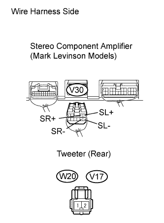
| 25.CHECK WIRE HARNESS (STEREO COMPONENT AMPLIFIER - SPEAKER (REAR)) |
Disconnect the V30 stereo component amplifier connector.
Disconnect the W20 and V17 speaker (rear) connectors.
Measure the resistance of the wire harness side connectors.
- Standard resistance:
Tester Connection
| Specified Condition
|
V30-1 (SL+) - W20-1
| Below 1 Ω
|
V30-5 (SL-) - W20-2
| Below 1 Ω
|
V30-2 (SR+) - V17-1
| Below 1 Ω
|
V30-6 (SR-) - V17-2
| Below 1 Ω
|
V30-1 (SL+) - Body ground
| 10 kΩ or higher
|
V30-5 (SL-) - Body ground
| 10 kΩ or higher
|
V30-2 (SR+) - Body ground
| 10 kΩ or higher
|
V30-6 (SR-) - Body ground
| 10 kΩ or higher
|
| | REPAIR OR REPLACE HARNESS AND CONNECTOR |
|
|
| OK |
|
|
|
| REPLACE STEREO COMPONENT AMPLIFIER |
|
| 26.INSPECT SPEAKER (WOOFER) |
Disconnect the V21 speaker (woofer) connector.
Measure the resistance of the connector.
- Standard resistance:
Tester Connection
| Specified Condition
|
1 - 2
| Approx. 14 Ω
|
3 - 4
| Approx. 14 Ω
|
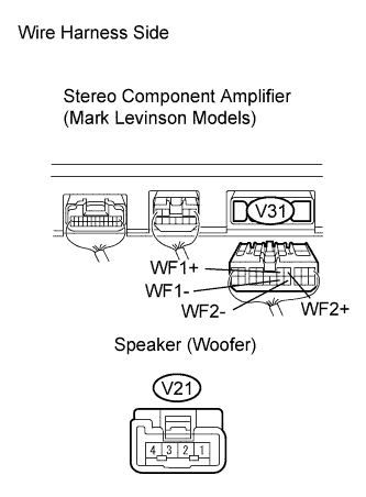
| 27.CHECK WIRE HARNESS (STEREO COMPONENT AMPLIFIER - SPEAKER WOOFER) |
Disconnect the V31 stereo component amplifier connector.
Disconnect the V21 speaker (woofer) connector.
Measure the resistance of the wire harness side connectors.
- Standard resistance:
Tester Connection
| Specified Condition
|
V31-5 (WF1+) - V21-4
| Below 1 Ω
|
V31-14 (WF1-) - V21-3
| Below 1 Ω
|
V31-4 (WF2+) - V21-2
| Below 1 Ω
|
V31-13 (WF2-) - V21-1
| Below 1 Ω
|
V31-5 (WF1+) - Body ground
| 10 kΩ or higher
|
V31-14 (WF1-) - Body ground
| 10 kΩ or higher
|
V31-4 (WF2+) - Body ground
| 10 kΩ or higher
|
V31-13 (WF2-) - Body ground
| 10 kΩ or higher
|
| | REPAIR OR REPLACE HARNESS AND CONNECTOR |
|
|
| OK |
|
|
|
| REPLACE STEREO COMPONENT AMPLIFIER |
|