Audio And Visual System Vehicle Speed Signal Circuit Between Stereo Component Amplifier And Combination Meter
DESCRIPTION
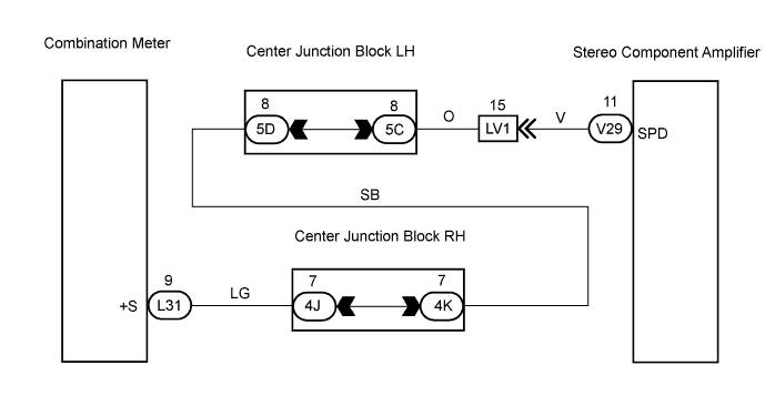
WIRING DIAGRAM
INSPECTION PROCEDURE
CHECK WIRE HARNESS (STEREO COMPONENT AMPLIFIER - COMBINATION METER)
CHECK COMBINATION METER ASSEMBLY
AUDIO AND VISUAL SYSTEM - Vehicle Speed Signal Circuit between Stereo Component Amplifier and Combination Meter |
DESCRIPTION
The stereo component amplifier's Auto Sound Levelizer (ASL) adjusts the audio volume in accordance with vehicle noise. For example, when vehicle noise increases, the ASL automatically increases the audio's volume. The ASL uses speed signals from the combination meter.
WIRING DIAGRAM
INSPECTION PROCEDURE
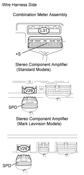
| 1.CHECK WIRE HARNESS (STEREO COMPONENT AMPLIFIER - COMBINATION METER) |
Disconnect the V29 stereo component amplifier and L31 combination meter assembly connectors.
Measure the resistance of the wire harness side connectors.
- Standard resistance:
Tester Connection
| Condition
| Specified Condition
|
V29-11 (SPD) - L31-9 (+S)
| Always
| Below 1 Ω
|
V29-11 (SPD) - Body ground
| Always
| 10 kΩ or higher
|
| | REPAIR OR REPLACE HARNESS AND CONNECTOR |
|
|
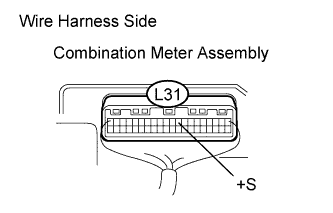
| 2.CHECK COMBINATION METER ASSEMBLY |
Jack up either of the rear wheels.
Move the shift lever to the neutral position.
Measure the voltage between the terminal +S and body ground while turning the jacked up rear wheel slowly.
- Standard voltage:
Tester Connection
| Condition
| Specification
|
L31-9 (+S) - Body ground
| Turning jacked up wheel slowly
| Voltage is pulsed
|
| | CHECK COMBINATION METER SYSTEM |
|
|
| OK |
|
|
|
| PROCEED TO NEXT CIRCUIT INSPECTION SHOWN IN PROBLEM SYMPTOMS TABLE |
|