Audio And Visual System Steering Pad Switch Circuit
DESCRIPTION
WIRING DIAGRAM
INSPECTION PROCEDURE
CHECK RADIO RECEIVER ASSEMBLY
INSPECT STEERING PAD SWITCH ASSEMBLY
INSPECT SPIRAL CABLE
AUDIO AND VISUAL SYSTEM - Steering Pad Switch Circuit |
DESCRIPTION
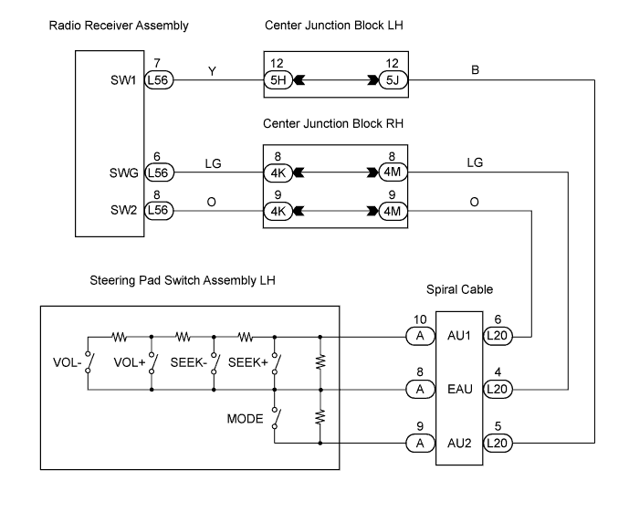
This circuit sends an operation signal from the steering pad switch to the radio receiver assembly. If there is an open in the circuit, the audio system cannot be operated by the steering pad switch. If there is a short in the circuit, the same condition as that when the switch is continuously depressed occurs. Therefore, the radio receiver assembly cannot be operated by the steering pad switch, and also the radio receiver assembly itself does not function.
WIRING DIAGRAM
INSPECTION PROCEDURE
| 1.CHECK RADIO RECEIVER ASSEMBLY |
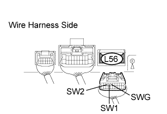
Disconnect the L56 receiver connector.
Measure the resistance of the wire harness side connector.
- Standard resistance:
Tester Connection
| Condition
| Specified Condition
|
L56-7 (SW1) - L56-6 (SWG)
| No switch is pushed
| Approx. 100 kΩ
|
L56-7 (SW1) - L56-6 (SWG)
| SEEK+ switch: pushed
| Approx. 0 Ω
|
L56-7 (SW1) - L56-6 (SWG)
| SEEK- switch: pushed
| Approx. 0.3 kΩ
|
L56-7 (SW1) - L56-6 (SWG)
| VOL+ switch: pushed
| Approx. 1 kΩ
|
L56-7 (SW1) - L56-6 (SWG)
| VOL- switch: pushed
| Approx. 3.2 kΩ
|
L56-8 (SW2) - L56-6 (SWG)
| No switch is pushed
| Approx. 100 kΩ
|
L56-8 (SW2) - L56-6 (SWG)
| MODE switch: pushed
| Approx. 0 Ω
|
| | REPLACE RADIO RECEIVER ASSEMBLY |
|
|
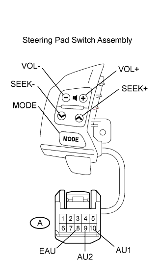
| 2.INSPECT STEERING PAD SWITCH ASSEMBLY |
Remove the steering pad switch.
Measure the resistance of the connector.
- Standard resistance:
Tester Connection
| Condition
| Specified Condition
|
A-10 (AU1) - A-8 (EAU)
| No switch is pushed
| Approx. 100 kΩ
|
A-10 (AU1) - A-8 (EAU)
| SEEK+ switch: pushed
| Approx. 0 kΩ
|
A-10 (AU1) - A-8 (EAU)
| SEEK- switch: pushed
| Approx. 0.3 kΩ
|
A-10 (AU1) - A-8 (EAU)
| VOL+ switch: pushed
| Approx. 1 kΩ
|
A-10 (AU1) - A-8 (EAU)
| VOL- switch: pushed
| Approx. 3.2 kΩ
|
A-9 (AU2) - A-8 (EAU)
| No switch is pushed
| Approx. 100 kΩ
|
A-9 (AU2) - A-8 (EAU)
| MODE switch: pushed
| Approx. 0 kΩ
|
| | REPLACE STEERING PAD SWITCH ASSEMBLY |
|
|
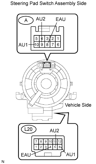
Disconnect the A steering pad switch and L20 spiral cable connectors.
Measure the resistance of the connectors.
- Standard resistance:
Tester Connection
| Specified Condition
|
L20-4 (EAU) - A-8 (EAU)
| Below 1 Ω
|
L20-6 (AU1) - A-10 (AU1)
| Below 1 Ω
|
L20-5 (AU2) - A-9 (AU2)
| Below 1 Ω
|
| OK |
|
|
|
| PROCEED TO NEXT CIRCUIT INSPECTION SHOWN IN PROBLEM SYMPTOMS TABLE |
|