Clearance Sonar System Power Source Of Clearance Warning Ecu Circuit
DESCRIPTION
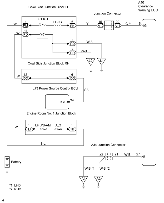
WIRING DIAGRAM
INSPECTION PROCEDURE
INSPECT FUSE (LH-IG)
INSPECT CLEARANCE WARNING ECU (IG TERMINAL VOLTAGE)
CHECK WIRE HARNESS (CLEARANCE WARNING ECU - BODY GROUND)
CLEARANCE SONAR SYSTEM - POWER SOURCE OF CLEARANCE WARNING ECU CIRCUIT |
DESCRIPTION
This circuit provides power to operate the clearance warning ECU.
WIRING DIAGRAM
INSPECTION PROCEDURE
Remove the LH-IG fuse from the cowl side junction block LH.
Measure the resistance of the LH-IG fuse.
- Standard resistance:
- Below 1 Ω
| 2.INSPECT CLEARANCE WARNING ECU (IG TERMINAL VOLTAGE) |
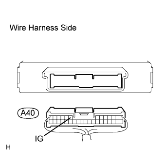
Disconnect the A40 ECU connector.
Measure the voltage of the wire harness side connector.
- Standard voltage:
Tester Connection
| Condition
| Specified Condition
|
A40-8 (IG) - Body ground
| Engine switch on (IG)
| 10 to 14 V
|
| | REPAIR OR REPLACE HARNESS AND CONNECTOR (CLEARANCE WARNING ECU - BATTERY) |
|
|
| 3.CHECK WIRE HARNESS (CLEARANCE WARNING ECU - BODY GROUND) |
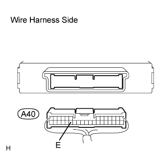
Disconnect the A40 ECU connector.
Measure the resistance of the wire harness side connector.
- Standard resistance:
Tester Connection
| Condition
| Specified Condition
|
A40-27 (E) - Body ground
| Always
| Below 1 Ω
|
| | REPAIR OR REPLACE HARNESS AND CONNECTOR |
|
|
| OK |
|
|
|
| REPLACE CLEARANCE WARNING ECU |
|