Rear Differential Carrier Assembly (For 3Uz-Fe) Disassembly
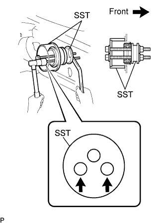
REMOVE NO.1 REAR DIFFERENTIAL MOUNT CUSHION
REMOVE NO.2 REAR DIFFERENTIAL MOUNT CUSHION
REMOVE REAR DIFFERENTIAL CARRIER COVER BREATHER PLUG
REMOVE REAR DIFFERENTIAL CARRIER COVER
REMOVE REAR DIFFERENTIAL BREATHER PLUG OIL DEFLECTOR
FIX REAR DIFFERENTIAL CARRIER
INSPECT RUNOUT OF DIFFERENTIAL RING GEAR
INSPECT DIFFERENTIAL RING GEAR BACKLASH
INSPECT REAR DIFFERENTIAL SIDE GEAR BACKLASH
INSPECT RUNOUT OF DIFFERENTIAL DRIVE PINION
INSPECT DIFFERENTIAL DRIVE PINION PRELOAD
INSPECT TOTAL PRELOAD
REMOVE REAR DIFFERENTIAL SIDE GEAR SHAFT OIL SEAL
REMOVE REAR DIFFERENTIAL SIDE GEAR SHAFT SNAP RING
REMOVE REAR DIFFERENTIAL SIDE GEAR SHAFT SNAP RING
REMOVE REAR DIFFERENTIAL CASE BEARING
REMOVE REAR DIFFERENTIAL CASE BEARING
REMOVE REAR DIFFERENTIAL CASE ASSEMBLY
REMOVE REAR DRIVE PINION NUT
REMOVE REAR DRIVE PINION COMPANION FLANGE
REMOVE REAR DIFFERENTIAL DUST DEFLECTOR
REMOVE REAR DIFFERENTIAL CARRIER OIL SEAL
REMOVE REAR DIFFERENTIAL DRIVE PINION OIL SLINGER
REMOVE DIFFERENTIAL DRIVE PINION
REMOVE REAR DIFFERENTIAL DRIVE PINION BEARING SPACER
REMOVE REAR DRIVE PINION FRONT TAPERED ROLLER BEARING
REMOVE REAR DRIVE PINION REAR TAPERED ROLLER BEARING
REMOVE DIFFERENTIAL RING GEAR
INSPECT RUNOUT OF REAR DIFFERENTIAL CASE ASSEMBLY
REMOVE REAR DIFFERENTIAL CASE BEARING
INSPECT DIFFERENTIAL PINION AND SIDE GEAR
Rear Differential Carrier Assembly (For 3Uz-Fe) -- Disassembly |
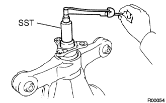
| 1. REMOVE NO.1 REAR DIFFERENTIAL MOUNT CUSHION |
- HINT:
- Perform this operation only when the No.1 rear differential mount cushion is damaged.
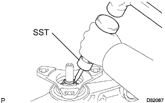
Using SST, remove the No.1 rear differential mount cushion.
- SST
- 09570-24010
09316-12010
- NOTICE:
- Do not bring SST into contact with the sub-frame.
- Do not slant the bolts of SST.
- Set the SST in the correct direction.
- Screw the 2 bolts of SST equally into the 2 holes of the rear differential mount.
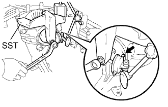
| 2. REMOVE NO.2 REAR DIFFERENTIAL MOUNT CUSHION |
- HINT:
- Perform this operation only when the No.2 rear differential mount cushion is damaged.
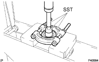
Using SST, remove the No.2 rear differential mount cushion.
- SST
- 09570-24010
09316-12010
- NOTICE:
- Do not bring SST into contact with the sub-frame.
- Do not slant the bolt of SST.
- Set the SST in the correct direction.
| 3. REMOVE REAR DIFFERENTIAL CARRIER COVER BREATHER PLUG |
Remove the breather plug from the differential carrier cover.
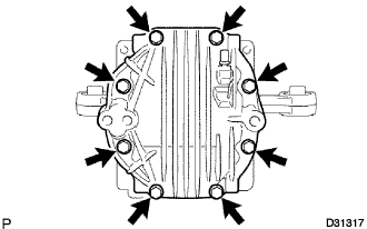
| 4. REMOVE REAR DIFFERENTIAL CARRIER COVER |
Remove the 8 bolts from the differential carrier cover.
Using a brass bar and a hammer, remove the differential carrier cover from the differential carrier.
| 5. REMOVE REAR DIFFERENTIAL BREATHER PLUG OIL DEFLECTOR |
Remove the bolt and oil deflector from the differential carrier cover.
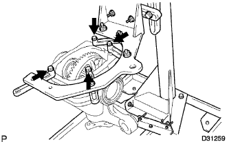
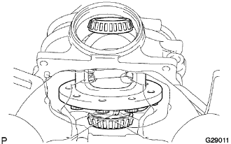
| 6. FIX REAR DIFFERENTIAL CARRIER |
Set the differential carrier to the overhaul stand, etc., as shown in the illustration.
| 7. INSPECT RUNOUT OF DIFFERENTIAL RING GEAR |
Set the dial indicator perpendicular to the end of the ring gear face.
Rotate the ring gear and measure the backlash.
- Maximum runout:
- 0.05 mm (0.0020 in.)
If runout exceeds the specified maximum value, remove the ring gear and check the runout of the differential case.
| 8. INSPECT DIFFERENTIAL RING GEAR BACKLASH |
While holding the rear drive pinion companion flange, rotate the ring gear and measure the backlash.
- Backlash:
- 0.08 to 0.13 mm (0.0031 to 0.0051 in.)
If the backlash is not within the specified range, adjust the backlash or repair as necessary.
| 9. INSPECT REAR DIFFERENTIAL SIDE GEAR BACKLASH |
Place a dial indicator on the tip of the pinion gear tooth at a right angle. Hold the side gear in the differential case and check that the backlash is 0 mm (0 in.).
If not, replace the rear differential case sub-assembly with a new one.
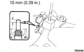
| 10. INSPECT RUNOUT OF DIFFERENTIAL DRIVE PINION |
Using a dial indicator, measure the runout of the drive pinion shaft at a position 10 mm (0.39 in.) away from the end of the shaft.
- Maximum runout:
- 0.08 mm (0.0031 in.)
If the runout is greater than the maximum, replace the drive pinion and ring gear.
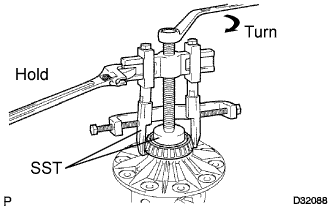
| 11. INSPECT DIFFERENTIAL DRIVE PINION PRELOAD |
Using SST and a torque wrench, measure the preload using the backlash of the drive pinion and ring gear.
- SST
- 09229-55010
- Drive pinion preload (at starting):
- 0.5 to 0.8 N*m (5 to 8 kgf*cm, 4.3 to 6.9 in.*lbf)
If the preload is not within the specified range, adjust the rear differential drive pinion preload or repair as necessary.
| 12. INSPECT TOTAL PRELOAD |
Using SST and a torque wrench, measure the preload with the teeth of the drive pinion and ring gear in contact.
- SST
- 09229-55010
- Total preload (at starting):
- Drive pinion preload plus 0.48 to 1.43 N*m (4.89 to 14.58 kgf*cm, 4.25 to 12.66 in.*lbf)
If necessary, disassemble and inspect the differential.
| 13. REMOVE REAR DIFFERENTIAL SIDE GEAR SHAFT OIL SEAL |
Using SST, remove the 2 oil seals.
- SST
- 09308-00010
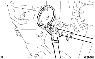
| 14. REMOVE REAR DIFFERENTIAL SIDE GEAR SHAFT SNAP RING |
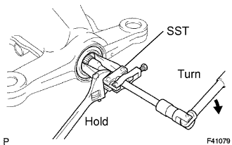
Install SST to the differential carrier.
- SST
- 09571-50010
Tighten the SST bolt until the SST disc lightly touches the case bearing outer race.
Install a dial indicator to the rear differential carrier.
Tighten the SST bolt and alter the differential carrier's shape to create a 0.1 mm (0.004 in.) clearance between the case bearing outer race and side gear shaft snap ring.
- NOTICE:
- Observe the dial indicator to ensure that the shape of the differential carrier does not change more than 0.2 mm (0.008 in.).
- HINT:
- Set the dial indicator to the rearmost position (upper side in the illustration) of the area around where the side gear shaft oil seal is tapped in.
- Approximately 0.1 mm (0.004 in.) clearance between the case bearing outer race and the side gear shaft snap ring is sufficient for the washer to move slightly.
Using snap ring pliers, remove the side gear shaft snap ring on the ring gear tooth side.
- HINT:
- For reassembly purposes, measure the thickness of the side gear shaft snap ring. Write down the result.
Remove the dial indicator and loosen the SST bolt.
- NOTICE:
- Do not remove the SST.
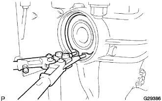
| 15. REMOVE REAR DIFFERENTIAL SIDE GEAR SHAFT SNAP RING |
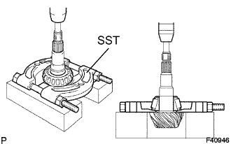
Using SST and a hammer, create a clearance between the case bearing outer race on the back surface of the ring gear and side gear shaft snap ring.
- SST
- 09608-32010
09950-70010(09951-07200)
- HINT:
- The clearance is not visible, but tapping the SST with a hammer three or four times should be enough.
Using snap ring pliers, remove the side gear shaft snap ring on the back surface of the ring gear.
- HINT:
- For reassembly purposes, measure the thickness of the side gear shaft snap ring. Write down the result.
| 16. REMOVE REAR DIFFERENTIAL CASE BEARING |
Tighten the SST bolt and push out the case bearing outer race on the back surface of the ring gear.
- SST
- 09571-50010
- NOTICE:
- Do not drop the case bearing outer race.
Remove the SST.
| 17. REMOVE REAR DIFFERENTIAL CASE BEARING |
Raise the ring gear of the differential case slightly to remove the ring gear tooth side case bearing outer race.
- HINT:
- For reassembly, check the installation position of the case bearing outer race and the side gear shaft shaft snap ring before removing the case bearing outer race. Write down the result.
| 18. REMOVE REAR DIFFERENTIAL CASE ASSEMBLY |
Remove rear differential case assembly.
- NOTICE:
- Do not damage the case bearing.
| 19. REMOVE REAR DRIVE PINION NUT |
Using SST and a hammer, unstake the staked part of the drive pinion nut.
- SST
- 09930-00010
- NOTICE:
- Be sure to use the SST with the tapered surface facing the shaft.
- Do not grind the tip of the SST with a grinder, etc.
- Completely loosen the staked part of the nut when removing it.
- Do not damage the threads of the drive pinion.
Using SST to hold the flange, remove the drive pinion nut.
- SST
- 09229-55010
09330-00021
09950-30012(09955-03040)
| 20. REMOVE REAR DRIVE PINION COMPANION FLANGE |
Using SST, remove the companion flange.
- SST
- 09950-30012(09951-03010,09953-03010,09954-03010,09955-03030,09956-03060)
- NOTICE:
- Apply grease to the threads and tip of the SST center bolt before use.
| 21. REMOVE REAR DIFFERENTIAL DUST DEFLECTOR |
- HINT:
- Perform this procedure only when the dust deflector is damaged.
Using SST and a press, remove the dust deflector.
- SST
- 09950-60010(09951-00440)
09950-00020
09950-70010(09951-07100)
| 22. REMOVE REAR DIFFERENTIAL CARRIER OIL SEAL |
Using SST, remove the oil seal from the differential carrier.
- SST
- 09308-10010
- NOTICE:
- Apply grease to the threads and tip of the SST center bolt before use.
| 23. REMOVE REAR DIFFERENTIAL DRIVE PINION OIL SLINGER |
Remove the drive pinion oil slinger.
| 24. REMOVE DIFFERENTIAL DRIVE PINION |
Using a press, remove the drive pinion form the differential carrier.
- NOTICE:
- Not drop the drive pinion.
| 25. REMOVE REAR DIFFERENTIAL DRIVE PINION BEARING SPACER |
Remove the drive pinion spacer.
| 26. REMOVE REAR DRIVE PINION FRONT TAPERED ROLLER BEARING |
Remove the rear drive pinion front tapered roller bearing inner race from the differential carrier.
Using a brass bar and a hammer, remove the rear drive pinion front tapered roller bearing outer race from the differential carrier.
| 27. REMOVE REAR DRIVE PINION REAR TAPERED ROLLER BEARING |
Using SST and a press, remove the rear drive pinion rear tapered roller bearing inner race from the drive pinion.
- SST
- 09950-00020
- HINT:
- If either the drive pinion or ring gear is damaged, replace both as a set.
Using a brass bar and a hammer, remove the rear drive pinion rear tapered roller bearing outer race from the differential carrier.
Remove the plate washer.
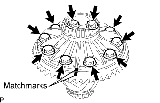
| 28. REMOVE DIFFERENTIAL RING GEAR |
Put machmarks on the ring gear and differential case.
Remove the 10 ring gear set bolts.
Using a plastic hammer, tap on the ring gear to separate it from the differential case.
| 29. INSPECT RUNOUT OF REAR DIFFERENTIAL CASE ASSEMBLY |
- HINT:
- Perform this procedure only when the runout of the differential ring gear exceeds the specified maximum value.
Install the differential case to the differential carrier.
- NOTICE:
- Do not damage the case bearing.
Using SST and a hammer, install the case bearing outer race on the ring gear tooth side.
- SST
- 09608-32010
09950-70010(09951-07200)
- HINT:
- Tap in the case bearing outer race until half of the side gear shaft snap ring groove of the differential carrier can be seen.
Install SST to the differential carrier.
- SST
- 09571-50010
Tighten the SST bolt until the SST disc lightly touches the case bearing outer race.
Using SST and a hammer, install the case bearing outer race on the ring gear back surfaces side.
- SST
- 09950-70010(09951-07200)
09608-32010
- HINT:
- Tap in the case bearing outer race until it touches the case bearing inner race roller.
Place a dial indicator on the differential case flange surface at a right angle.
Using a dial indicator, measure the differential case runout.
- Maximum runout:
- 0.05 mm (0.0020 in.)
If the runout is greater than the maximum, replace the rear differential case with a new one.
Tighten the SST bolt to push out the ring gear back surfaces side case bearing outer race.
- SST
- 09571-50010
- NOTICE:
- Do not drop the case bearing outer race.
Remove the SST.
Raise the ring gear side of the differential case slightly to remove the ring gear tooth side case bearing outer race.
Remove the differential case from the differential carrier.
- NOTICE:
- Do not damage the case bearing.
| 30. REMOVE REAR DIFFERENTIAL CASE BEARING |
- HINT:
- Perform this procedure only when replacing the case bearing or differential case.
Using SST, remove the case bearing inner race LH and RH from the differential case.
- SST
- 09950-60010(09951-00480)
09950-40011(09951-04020,09952-04010,09953-04030,09954-04010,09955-04061,09957-04010,09958-04011)
- NOTICE:
- Do not deform the bearing cage if the bearing is to be reused.
- Hook the SST claw from the dent of the differential case to the bearing inner race.
- Apply grease to the threads and tip of the SST center bolt before use.
| 31. INSPECT DIFFERENTIAL PINION AND SIDE GEAR |
Hold the differential case in a vise between aluminum plates.
- NOTICE:
- Do not overtighten the vise.
Place a dial indicator on the tip of the side gear tooth at a right angle. Hold the pinion gear in the differential case and check that the backlash is 0 mm (0 in.).
If not replace the rear differential case sub-assembly with a new one.