Navigation System Parking Brake Switch Circuit
DESCRIPTION
WIRING DIAGRAM
INSPECTION PROCEDURE
CHECK PARKING BRAKE SWITCH ASSEMBLY
CHECK HARNESS AND CONNECTOR (NAVIGATION RECEIVER ASSEMBLY - PARKING BRAKE SWITCH ASSEMBLY)
INSPECT PARKING BRAKE SWITCH ASSEMBLY
NAVIGATION SYSTEM - Parking Brake Switch Circuit |
DESCRIPTION
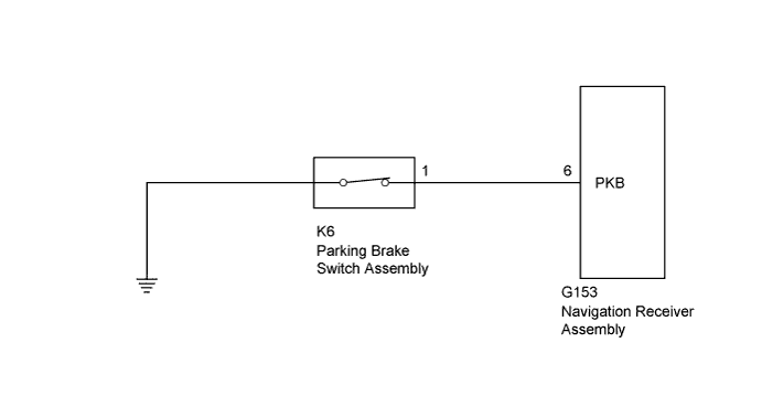
This circuit includes the parking brake switch and navigation receiver assembly.
WIRING DIAGRAM
INSPECTION PROCEDURE
| 1.CHECK PARKING BRAKE SWITCH ASSEMBLY |
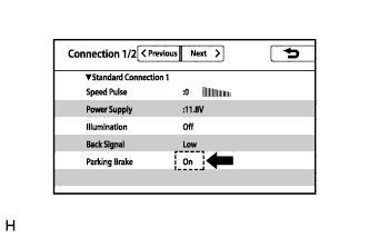
Display the "Connection Status" screen (HILUX_TGN26 RM000003A3N028X.html).
Check that the display changes between On and Off according to the parking brake operation.
- OK:
Parking Brake Condition
| Display
|
Applied
| On
|
Released
| Off
|
- HINT:
- This display is updated once per second. As a result, it is normal for the display to lag behind the actual parking brake operation.
| 2.CHECK HARNESS AND CONNECTOR (NAVIGATION RECEIVER ASSEMBLY - PARKING BRAKE SWITCH ASSEMBLY) |
Disconnect the G153 navigation receiver assembly connector.
Disconnect the K6 parking brake switch assembly connector.
Measure the resistance according to the value(s) in the table below.
- Standard Resistance:
Tester Connection
| Condition
| Specified Condition
|
G153-6 (PKB) - K6-1
| Always
| Below 1 Ω
|
G153-6 (PKB) - Body ground
| Always
| 10 kΩ or higher
|
| | REPAIR OR REPLACE HARNESS OR CONNECTOR |
|
|
| 3.INSPECT PARKING BRAKE SWITCH ASSEMBLY |
Remove the parking brake switch assembly (HILUX_TGN26 RM000001C4X01LX.html).
Measure the resistance according to the value(s) in the table below.
- Standard Resistance:
Tester Connection
| Switch Condition
| Specified Condition
|
Switch connector terminal - Switch body
| On (Shaft not pressed)
| Below 1 Ω
|
Off (Shaft pressed)
| 10 kΩ or higher
|
Text in Illustration
| On
|

| Off
|
If the result is not as specified, replace the parking brake switch assembly.