Can Communication System (W/ Vsc) Steering Angle Sensor Communication Stop Mode
Networking. Hilux. Tgn26, 36 Kun25, 26, 35, 36 Ggn25
DESCRIPTION
WIRING DIAGRAM
INSPECTION PROCEDURE
PRECAUTION
DISCONNECT CABLE FROM NEGATIVE BATTERY TERMINAL
CHECK FOR OPEN IN CAN BUS WIRE (STEERING ANGLE SENSOR CAN BRANCH WIRE)
CHECK HARNESS AND CONNECTOR (STEERING ANGLE SENSOR - BATTERY AND BODY GROUND)
CAN COMMUNICATION SYSTEM (w/ VSC) - Steering Angle Sensor Communication Stop Mode |
DESCRIPTION
Detection Item
| Symptom
| Trouble Area
|
Steering Angle Sensor Communication Stop Mode
| Either condition is met:
- "Spiral cable (Steering Angle Sensor)" is not displayed on the "Bus Check" screen.
- "Steering Angle Sensor Communication Stop Mode" in "DTC Communication Table" applies.
| - Power source or inside of spiral cable sub-assembly (steering angle sensor)
- Spiral cable sub-assembly (steering angle sensor) CAN branch wire or connector
- Spiral cable sub-assembly (steering angle sensor)
|
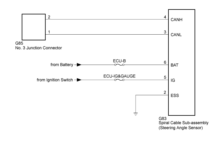
WIRING DIAGRAM
INSPECTION PROCEDURE
- NOTICE:
- Inspect the fuses for circuits related to this system before performing the following inspection procedure.
- HINT:
- Operating the ignition switch, any switches or any doors triggers related ECU and sensor communication with the CAN, which causes resistance variation.
- NOTICE:
- After turning the ignition switch off, waiting time may be required before disconnecting the cable from the battery terminal. Therefore, make sure to read the disconnecting the cable from the battery terminal notice before proceeding with work (HILUX_TGN26 RM000004QR1006X.html).
| 2.DISCONNECT CABLE FROM NEGATIVE BATTERY TERMINAL |
Disconnect the cable from the negative (-) battery terminal before measuring the resistances of the CAN main wire and the CAN branch wire.
- CAUTION:
- Wait at least 90 seconds after disconnecting the cable from the negative (-) battery terminal to disable the SRS system.
- NOTICE:
- When disconnecting the cable, some systems need to be initialized after the cable is reconnected (HILUX_TGN26 RM000004QR3008X.html).
| 3.CHECK FOR OPEN IN CAN BUS WIRE (STEERING ANGLE SENSOR CAN BRANCH WIRE) |
Disconnect the G83 spiral cable sub-assembly (steering angle sensor) connector.
Measure the resistance according to the value(s) in the table below.
- Standard Resistance:
Tester Connection
| Switch Condition
| Specified Condition
|
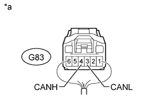
G83-4 (CANH) - G83-3 (CANL)
| Ignition switch off
| 54 to 69 Ω
|
Text in Illustration*a
| Rear view of wire harness connector
(to Spiral Cable Sub-assembly [Steering Angle Sensor])
|
| | REPAIR OR REPLACE STEERING ANGLE SENSOR CAN BRANCH WIRE OR CONNECTOR (CANH, CANL) |
|
|
| 4.CHECK HARNESS AND CONNECTOR (STEERING ANGLE SENSOR - BATTERY AND BODY GROUND) |
Connect the cable to the negative (-) battery terminal.
- NOTICE:
- When disconnecting the cable, some systems need to be initialized after the cable is reconnected (HILUX_TGN26 RM000004QR3008X.html).
Measure the voltage according to the value(s) in the table below.
- Standard Voltage:
Tester Connection
| Condition
| Specified Condition
|
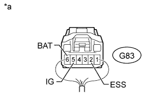
G83-6 (BAT) - Body ground
| Always
| 11 to 14 V
|
G83-5 (IG) - Body ground
| Ignition switch ON
| 11 to 14 V
|
Measure the resistance according to the value(s) in the table below.
- Standard Resistance:
Tester Connection
| Condition
| Specified Condition
|
G83-2 (ESS) - Body ground
| Always
| Below 1 Ω
|
Text in Illustration*a
| Rear view of wire harness connector
(to Spiral Cable Sub-assembly [Steering Angle Sensor])
|
| | REPAIR OR REPLACE HARNESS OR CONNECTOR |
|
|