Theft Deterrent System Starter Relay Circuit
DESCRIPTION
WIRING DIAGRAM
INSPECTION PROCEDURE
INSPECT ST RELAY
INSPECT IGNITION SWITCH ASSEMBLY
CHECK VEHICLE TYPE
INSPECT PARK/NEUTRAL POSITION SWITCH ASSEMBLY
CHECK HARNESS AND CONNECTOR (ST RELAY - BATTERY)
CHECK HARNESS AND CONNECTOR (THEFT WARNING ECU - BATTERY AND BODY GROUND)
THEFT DETERRENT SYSTEM - Starter Relay Circuit |
DESCRIPTION
When the theft deterrent system operates, the theft warning ECU assembly deactivates the ST relay so that the starter cannot crank the engine.
WIRING DIAGRAM
INSPECTION PROCEDURE
- NOTICE:
- If the engine cranks but does not start, there is a problem with the SFI system*1 or ECD system*2. If this is the case, refer to SFI System*1 or ECD System*2 and perform troubleshooting.
- *1: for 2TR-FE, 2TR-FBE, 1GR-FE
- *2: for 1KD-FTV, 2KD-FTV
- Inspect the fuses for circuits related to this system before performing the following inspection procedure.
- When replacing the theft warning ECU assembly, refer to the registration procedures (HILUX_TGN26 RM000000Z4Z01KX.html).
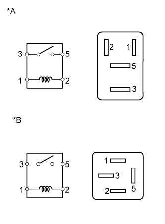
Remove the ST relay from the engine room relay block and junction block assembly.
Measure the resistance according to the value(s) in the table below.
- Standard Resistance:
Tester Connection
| Condition
| Specified Condition
|
3 - 5
| Battery voltage is not applied to terminals 1 and 2
| 10 kΩ or higher
|
Battery voltage is applied to terminals 1 and 2
| Below 1 Ω
|
Text in Illustration*A
| for 2TR-FE, 2TR-FBE, 1GR-FE
|
*B
| for 1KD-FTV, 2KD-FTV
|
| 2.INSPECT IGNITION SWITCH ASSEMBLY |
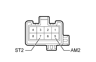
Remove the ignition switch assembly.
- for 2TR-FE: HILUX_TGN26 RM00000135Z01BX.html
- for 2TR-FBE: HILUX_TGN26 RM00000135Z01GX.html
- for 1GR-FE: HILUX_TGN26 RM00000135Z01OX.html
- for 1KD-FTV: HILUX_TGN26 RM0000013XF01HX.html
- for 2KD-FTV: HILUX_TGN26 RM0000013XF01IX.html
Measure the resistance according to the value(s) in the table below.
- Standard Resistance:
Tester Connection
| Switch Condition
| Specified Condition
|
5 (AM2) - 7 (ST2)
| Off, ACC, ON
| 10 kΩ or higher
|
Start
| Below 1 Ω
|
- HINT:
If replacing the park/neutral position switch assembly, refer to the procedures below.
- for 2TR-FE: HILUX_TGN26 RM00000135Z01BX.html
- for 2TR-FBE: HILUX_TGN26 RM00000135Z01GX.html
- for 1GR-FE: HILUX_TGN26 RM00000135Z01OX.html
- for 1KD-FTV: HILUX_TGN26 RM0000013XF01HX.html
- for 2KD-FTV: HILUX_TGN26 RM0000013XF01IX.html
| | REPLACE IGNITION SWITCH ASSEMBLY |
|
|
Check the vehicle type.
ResultResult
| Proceed to
|
for Automatic Transmission
| A
|
for Manual Transmission
| B
|
| 4.INSPECT PARK/NEUTRAL POSITION SWITCH ASSEMBLY |
Remove the park/neutral position switch assembly.
- for A750F: HILUX_TGN26 RM0000010NC06DX.html
- for A340F: HILUX_TGN26 RM0000010NC05IX.html
- for A343F: HILUX_TGN26 RM0000010NC05LX.html
- for A343E: HILUX_TGN26 RM0000010NC05PX.html
Measure the resistance according to the value(s) in the table below.
- Standard Resistance:
Tester Connection
| Switch Condition
| Specified Condition
|
4 - 5
| Shift lever in P or N
| Below 1 Ω
|
Shift lever not in P and N
| 10 kΩ or higher
|
ResultResult
| Proceed to
|
OK
| A
|
NG (for A750F)
| B
|
NG (for A340F)
| C
|
NG (for A343F)
| D
|
NG (for A343E)
| E
|
| 5.CHECK HARNESS AND CONNECTOR (ST RELAY - BATTERY) |
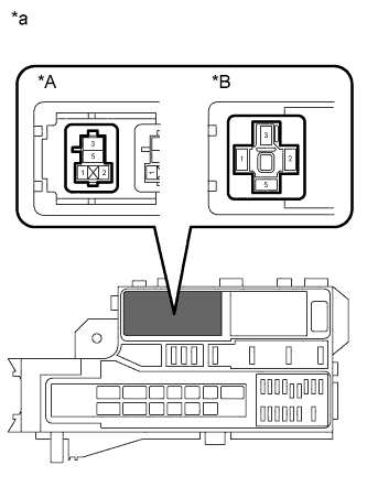
Remove the ST relay from the engine room relay block.
Measure the voltage according to the value(s) in the table below.
- Standard Voltage:
Tester Connection
| Condition
| Specified Condition
|
Relay block ST relay terminal 5 - Body ground
| Always
| 11 to 14 V
|
Text in Illustration*A
| for 2TR-FE, 2TR-FBE, 1GR-FE
|
*B
| for 1KD-FTV, 2KD-FTV
|
*a
| Front view of wire harness connector
(to ST Relay)
|
| | REPAIR OR REPLACE HARNESS OR CONNECTOR |
|
|
| 6.CHECK HARNESS AND CONNECTOR (THEFT WARNING ECU - BATTERY AND BODY GROUND) |
Disconnect the G29 theft warning ECU assembly connector.
Measure the resistance according to the value(s) in the table below.
- Standard Resistance:
Tester Connection
| Condition
| Specified Condition
|
G29-1 (E) - Body ground
| Always
| Below 1 Ω
|
Measure the voltage according to the value(s) in the table below.
- Standard Voltage:
Tester Connection
| Switch Condition
| Specified Condition
|
G29-12 (SRLY) - Body ground
| Ignition switch off
| Below 1 V
|
Ignition switch ON
| 11 to 14 V
|
Text in Illustration*a
| Front view of wire harness connector
(to Theft Warning ECU Assembly)
|
| | REPAIR OR REPLACE HARNESS OR CONNECTOR |
|
|