Clutch Unit -- Inspection |
| 1. INSPECT CLUTCH DISC ASSEMBLY |
Using a vernier caliper, measure the rivet head depth.
- Minimum rivet head depth:
- 0.3 mm (0.0118 in.)
 |
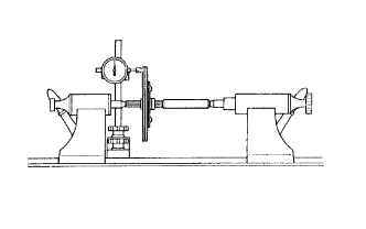
Using a dial indicator, check the disc runout.
- Maximum runout:
- 0.8 mm (0.0314 in.)
- NOTICE:
- Be sure to measure on the correct side of the clutch disc.
 |
| 2. INSPECT CLUTCH COVER ASSEMBLY |
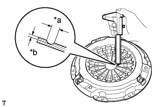
Using a vernier caliper, measure the depth and width of the worn areas of the diaphragm spring.
Text in Illustration *a Width *b Depth - Maximum width:
- 6.0 mm (0.236 in.)
- Maximum depth:
- 0.35 mm (0.0137 in.)
 |
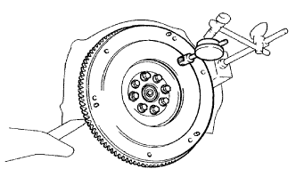
| 3. INSPECT FLYWHEEL SUB-ASSEMBLY |
Using a dial indicator, measure the flywheel runout.
- Maximum runout:
- 0.1 mm (0.00393 in.)
 |
| 4. INSPECT CLUTCH RELEASE BEARING ASSEMBLY |
Turn the bearing by hand while applying force in the axial direction and check that the bearing rotates smoothly.
If the bearing sticks or a considerable amount of resistance is felt, replace the release bearing.- HINT:
- The bearing is permanently lubricated and requires no cleaning or lubrication.
 |
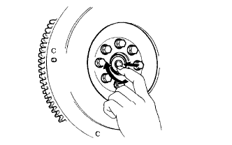
| 5. INSPECT INPUT SHAFT FRONT BEARING |
Turn the bearing by hand while applying rotational force and check that the bearing rotates smoothly.
If the bearing sticks or a considerable amount of resistance is felt, replace the input shaft front bearing.- HINT:
- The bearing is permanently lubricated and requires no cleaning or lubrication.
 |
| 6. REPLACE INPUT SHAFT FRONT BEARING |
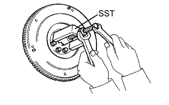
Remove any 2 diametrically opposite bolts.
Using SST, remove the input shaft front bearing.
- SST
- 09303-35011
 |
Using SST and a hammer, tap in a new bearing.
- SST
- 09304-12012
- HINT:
- After installing the bearing to the crankshaft, make sure that it rotates smoothly.
 |
Apply adhesive to 2 or 3 threads of the bolts.
- Adhesive:
- Toyota Genuine Adhesive 1324, Three Bond 1324 or equivalent
for TR Engine series:
Install the 2 bolts.
- Torque:
- 27 N*m{270 kgf*cm, 20 ft.*lbf}
- HINT:
- The mounting bolts are tightened in 2 progressive steps.
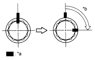
Mark the mounting bolts with paint.
Text in Illustration *a Paint Mark *b 90° Retighten the mounting bolts by 90°.
Check that the paint marks are now at a 90° angle to the original marked position.
for 1KD-FTV, 2KD-FTV:
Apply adhesive to 2 or 3 threads of the bolts.
- Adhesive:
- Toyota Genuine Adhesive 1324, Three Bond 1324 or equivalent
Install the 2 bolts.
- Torque:
- 178 N*m{1815 kgf*cm, 131 ft.*lbf}