Automatic Transmission System L4 Position Switch Circuit
Drivetrain. Hilux. Tgn26, 36 Kun25, 26, 35, 36 Ggn25
DESCRIPTION
WIRING DIAGRAM
INSPECTION PROCEDURE
CHECK HARNESS AND CONNECTOR (NO. 1 TRANSFER INDICATOR SWITCH - BODY GROUND)
INSPECT NO. 1 TRANSFER INDICATOR SWITCH (L4 POSITION SWITCH)
CHECK HARNESS AND CONNECTOR (NO. 1 TRANSFER INDICATOR SWITCH - TCM)
AUTOMATIC TRANSMISSION SYSTEM - L4 Position Switch Circuit |
DESCRIPTION
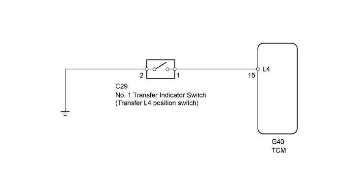
The No. 1 transfer indicator switch (L4 position switch) detects the gear position of the transfer shift lever. Moving the transfer shift lever to L4 turns the L4 position switch is on. Then the TCM cancels operation of the lock-up clutch.
WIRING DIAGRAM
INSPECTION PROCEDURE
| 1.CHECK HARNESS AND CONNECTOR (NO. 1 TRANSFER INDICATOR SWITCH - BODY GROUND) |
Disconnect the C29 No. 1 transfer indicator switch connector.
Measure the resistance according to the value(s) in the table below.
- Standard Resistance:
Tester Connection
| Condition
| Specified Condition
|
C29-2 - Body ground
| Always
| Below 1 Ω
|
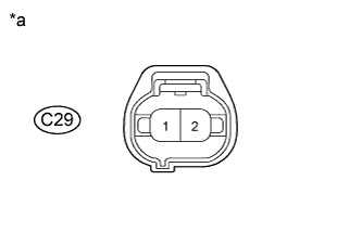
Text in Illustration*a
| Front view of wire harness connector:
(to No. 1 Transfer Indicator Switch)
|
| | REPAIR OR REPLACE HARNESS AND CONNECTOR |
|
|
| 2.INSPECT NO. 1 TRANSFER INDICATOR SWITCH (L4 POSITION SWITCH) |
Remove the No. 1 transfer indicator switch.
Measure the resistance according to the value(s) in the table below.
- Standard Resistance:
Tester Connection
| Switch Condition
| Specified Condition
|
1 - 2
| Not pushed
| 10 kΩ or higher
|
1 - 2
| Pushed
| Below 1 Ω
|
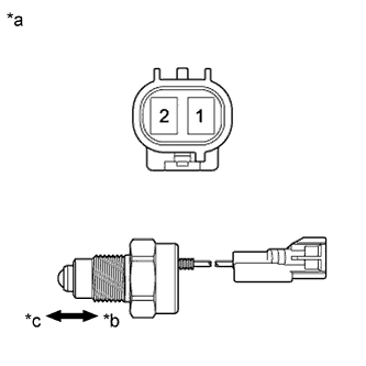
Text in Illustration*a
| Component without harness connected
(No. 1 transfer indicator switch)
|
*b
| Pushed
|
*c
| Not pushed
|
| 3.CHECK HARNESS AND CONNECTOR (NO. 1 TRANSFER INDICATOR SWITCH - TCM) |
Disconnect the C29 No. 1 transfer indicator switch connector.
Disconnect the G40 TCM connector.
Measure the resistance according to the value(s) in the table below.
- Standard Resistance:
Tester Connection
| Condition
| Specified Condition
|
G40-15 (L4) - C29-1
| Always
| Below 1 Ω
|
G40-15 (L4) or C29-1 Body ground
| Always
| 10 kΩ or higher
|
| | REPAIR OR REPLACE HARNESS AND CONNECTOR |
|
|