Intake Manifold (For Dpf) Removal
PRECAUTION
DISCONNECT CABLE FROM NEGATIVE BATTERY TERMINAL
REMOVE ELECTRIC EGR CONTROL VALVE ASSEMBLY WITH NO. 2 EGR VALVE AND EGR COOLER
REMOVE NO. 4 INJECTION PIPE SUB-ASSEMBLY
DISCONNECT WIRING HARNESS CLAMP BRACKET
REMOVE NO. 2 FUEL PIPE
REMOVE NO. 3 NOZZLE LEAKAGE PIPE
REMOVE NO. 2 NOZZLE LEAKAGE PIPE ASSEMBLY
REMOVE GLOW CONNECTOR BRACKET
REMOVE NO. 3 INTERCOOLER SUPPORT BRACKET
REMOVE NO. 2 MANIFOLD STAY
REMOVE NO. 1 GLOW PLUG CONNECTOR
REMOVE NO. 1 INTAKE MANIFOLD INSULATOR
REMOVE INTAKE MANIFOLD INSULATOR
REMOVE INTAKE MANIFOLD
Intake Manifold (For Dpf) -- Removal |
- NOTICE:
- When replacing the injectors (including shuffling the injectors between the cylinders), common rail or cylinder head, it is necessary to replace the injection pipes with new ones.
- When replacing the fuel supply pump, common rail, cylinder block, cylinder head, cylinder head gasket or timing gear case, it is necessary to replace the fuel inlet pipe with a new one.
- After removing the injection pipes and fuel inlet pipe, clean them with a brush and compressed air.
- NOTICE:
- After turning the ignition switch off, waiting time may be required before disconnecting the cable from the battery terminal. Therefore, make sure to read the disconnecting the cable from the battery terminal notice before proceeding with work (HILUX_TGN26 RM000004QR1006X.html).
| 2. DISCONNECT CABLE FROM NEGATIVE BATTERY TERMINAL |
- NOTICE:
- When disconnecting the cable, some systems need to be initialized after the cable is reconnected (HILUX_TGN26 RM000004QR3009X.html).
| 3. REMOVE ELECTRIC EGR CONTROL VALVE ASSEMBLY WITH NO. 2 EGR VALVE AND EGR COOLER |
(HILUX_TGN26 RM000004QWO008X.html)
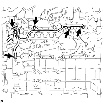
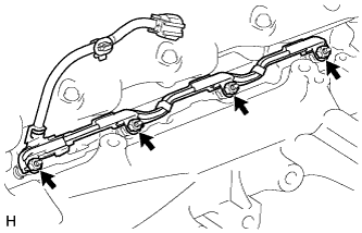
| 4. REMOVE NO. 4 INJECTION PIPE SUB-ASSEMBLY |
Remove the bolt, nut and 2 No. 2 injection pipe clamps.
Using a 17 mm union nut wrench, loosen the union nuts and remove the No. 4 injection pipe.
| 5. DISCONNECT WIRING HARNESS CLAMP BRACKET |
| 6. REMOVE NO. 2 FUEL PIPE |
Using a 6 mm hexagon wrench, remove the supply pump hollow screw and gasket.
Text in Illustration
| Bolt
|

| Supply Pump Hollow Screw
|

| Fuel Check Valve
|

| Union Bolt
|
Remove the fuel check valve, union bolt and 2 gaskets.
Remove the 3 bolts and No. 2 fuel pipe.
| 7. REMOVE NO. 3 NOZZLE LEAKAGE PIPE |
Disconnect the 3 fuel hoses.
Text in Illustration
| Fuel Check Valve
|
Remove the 2 bolts.
Remove the fuel check valve, gasket and No. 3 nozzle leakage pipe.
| 8. REMOVE NO. 2 NOZZLE LEAKAGE PIPE ASSEMBLY |
Remove the 2 bolts.
Text in Illustration
| Union Bolt
|
Remove the union bolt, gasket and No. 2 nozzle leakage pipe.
| 9. REMOVE GLOW CONNECTOR BRACKET |
Disconnect the No. 1 glow plug connector and detach the clamp.
Remove the bolt and glow connector bracket.
| 10. REMOVE NO. 3 INTERCOOLER SUPPORT BRACKET |
Remove the bolt and No. 3 intercooler support bracket.
| 11. REMOVE NO. 2 MANIFOLD STAY |
Remove the bolt and No. 2 manifold stay.
| 12. REMOVE NO. 1 GLOW PLUG CONNECTOR |
Remove the 4 screw grommets.
Remove the 4 nuts and No. 1 glow plug connector.
| 13. REMOVE NO. 1 INTAKE MANIFOLD INSULATOR |
| 14. REMOVE INTAKE MANIFOLD INSULATOR |
Remove the intake manifold insulator.
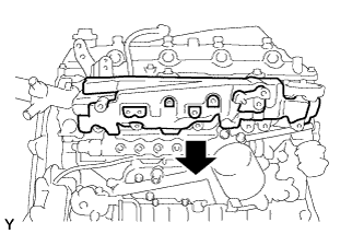
| 15. REMOVE INTAKE MANIFOLD |
Remove the bolt and disconnect the fuel hose protector from the intake manifold.
Detach the sensor wire connector clamp from the intake manifold.
Remove the 4 bolts, 2 nuts, intake manifold and gasket.