Dtc C1622 Open Or Short Circuit In Back Camera Signal
DESCRIPTION
WIRING DIAGRAM
INSPECTION PROCEDURE
CHECK FOR DTC
CHECK HARNESS AND CONNECTOR (NAVIGATION RECEIVER ASSEMBLY - REAR TELEVISION CAMERA ASSEMBLY)
CHECK NAVIGATION RECEIVER ASSEMBLY
CHECK NAVIGATION RECEIVER ASSEMBLY
CHECK REAR TELEVISION CAMERA ASSEMBLY
REPLACE REAR TELEVISION CAMERA ASSEMBLY
CHECK FOR DTC
DTC C1622 Open or Short Circuit in Back Camera Signal |
DESCRIPTION
This DTC is stored if the navigation receiver assembly judges as a result of its self check that the signals or signal lines between the navigation receiver assembly and the rear television camera assembly are not normal.DTC Code
| DTC Detection Condition
| Trouble Area
|
C1622
| Open or Short Circuit in rear television camera signal
| - Harness or connector
- Rear television camera assembly
- Navigation receiver assembly
|
WIRING DIAGRAM
INSPECTION PROCEDURE
Clear the DTCs (HILUX_TGN26 RM0000051N6002X.html).
Check for DTCs (HILUX_TGN26 RM0000051N6002X.html).
ResultResult
| Proceed to
|
No DTC is output
| A
|
DTC is output
| B
|
| 2.CHECK HARNESS AND CONNECTOR (NAVIGATION RECEIVER ASSEMBLY - REAR TELEVISION CAMERA ASSEMBLY) |
Disconnect the G153 navigation receiver assembly connector.
Disconnect the M2 rear television camera assembly connector.
Measure the resistance according to the value(s) in the table below.
- Standard Resistance:
Tester Connection
| Condition
| Specified Condition
|
G153-7 (CA+) - M2-4 (CB+)
| Always
| Below 1 Ω
|
G153-8 (V+) - M2-2 (CV+)
| Always
| Below 1 Ω
|
G153-15 (CGND) - M2-3 (CGND)
| Always
| Below 1 Ω
|
G153-16 (V-) - M2-1 (CV-)
| Always
| Below 1 Ω
|
G153-7 (CA+) - Body ground
| Always
| 10 kΩ or higher
|
G153-8 (V+) - Body ground
| Always
| 10 kΩ or higher
|
G153-15 (CGND) - Body ground
| Always
| 10 kΩ or higher
|
G153-16 (V-) - Body ground
| Always
| 10 kΩ or higher
|
| | REPAIR OR REPLACE HARNESS OR CONNECTOR |
|
|
| 3.CHECK NAVIGATION RECEIVER ASSEMBLY |
Disconnect the G153 navigation receiver assembly connector.
Measure the resistance according to the value(s) in the table below.
- Standard Resistance:
Tester Connection
| Condition
| Specified Condition
|
G153-15 (CGND) - Body ground
| Always
| Below 1 Ω
|
G153-16 (V-) - Body ground
| Always
| Below 1 Ω
|
Text in Illustration*a
| Component without harness connected
(Navigation Receiver Assembly)
|
| 4.CHECK NAVIGATION RECEIVER ASSEMBLY |
Disconnect the M2 rear television camera assembly connector.
Measure the voltage according to the value(s) in the table below.
- Standard Voltage:
Tester Connection
| Condition
| Specified Condition
|
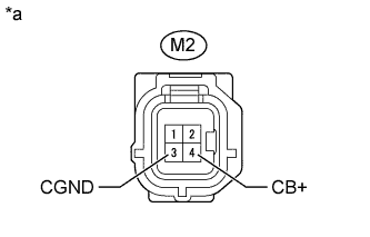
M2-4 (CB+) - M4-3 (CGND)
| Ignition switch ON, shift lever in R
| 5.5 to 7.05 V
|
Text in Illustration*a
| Front view of wire harness connector
(to Rear Television Camera Assembly)
|
| 5.CHECK REAR TELEVISION CAMERA ASSEMBLY |
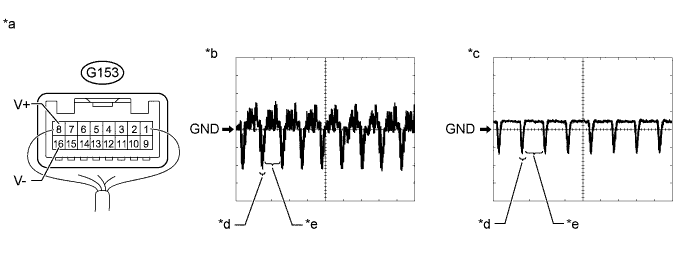
Using an oscilloscope, check the waveform.
Text in Illustration*a
| Component with harness connected
(Navigation Receiver Assembly)
| *b
| Waveform 1
|
*c
| Waveform 2
| *d
| Synchronized Signal
|
*e
| Video Waveform
| -
| -
|
Measurement ConditionItem
| Content
|
Tester Connection
| G153-8(V+) - G153-16 (V-)
|
Tool Setting
| 0.2 V/DIV., 50 μs/DIV.
|
Condition
| - Waveform 1: Ignition switch ON, shift lever in R
- Waveform 2: Ignition switch ON, shift lever in R, screen blacked out by covering camera lens
|
- OK:
- Waveform is as shown in illustration.
- HINT:
- The video waveform changes according to the image sent by the rear television camera assembly.
| 6.REPLACE REAR TELEVISION CAMERA ASSEMBLY |
Replace the rear television camera assembly with a new or normally functioning one (HILUX_TGN26 RM00000139200NX.html).
Clear the DTCs (HILUX_TGN26 RM0000051N6002X.html).
Check for DTCs (HILUX_TGN26 RM0000051N6002X.html).
ResultResult
| Proceed to
|
No DTC is output
| A
|
DTC is output
| B
|
| OK |
|
|
|
| END (REAR TELEVISION CAMERA ASSEMBLY WAS DEFECTIVE) |
|