Exhaust Fuel Addition Injector -- Installation |
| 1. INSTALL EXHAUST FUEL ADDITION INJECTOR ASSEMBLY |
- NOTICE:
- If there is foreign matter on the installation surface of the exhaust fuel addition injector, be sure to clean it before installation.
Install a new E-ring, a new O-ring and 3 new backup rings to the exhaust fuel addition injector.
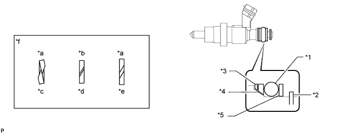
Text in Illustration *1 O-Ring *2 E-Ring *3 No. 1 Backup Ring *4 No. 2 Backup Ring *5 No. 3 Backup Ring - - *a Incorrect *b Correct *c Overlapped *d Normal *e Stretched *f Alignment Opening - NOTICE:
- Check that there is no foreign matter or damaged areas in the injector O-ring groove.
- Check that the No. 1 and No. 2 backup rings are installed in the correct direction.
- Make sure that the backup rings and O-ring are installed in the correct order.
- Check that the alignment openings of the backup rings are not stretched and that the ends of the backup rings are not overlapped as shown in the illustration.
- After installing the O-ring, check that it is not contaminated with foreign matter and is not damaged.
Install a new gasket and the exhaust fuel addition injector.
Using a T40 "TORX" socket wrench, install the No. 1 nozzle holder clamp with the screw.
- Torque:
- 10 N*m{102 kgf*cm, 7 ft.*lbf}
Install the injector holder with the 2 bolts.
- Torque:
- 28 N*m{286 kgf*cm, 21 ft.*lbf}
| 2. INSTALL TURBINE OUTLET ELBOW |
| 3. CONNECT CABLE TO NEGATIVE BATTERY TERMINAL |
- NOTICE:
- When disconnecting the cable, some systems need to be initialized after the cable is reconnected (HILUX_TGN26 RM000004QR300CX.html).
| 4. ADD ENGINE COOLANT |
| 5. BLEED AIR FROM FUEL SYSTEM |
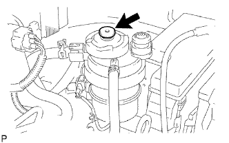
Using the hand pump mounted on the fuel filter cap, bleed the air from the fuel system. Continue pumping until the pump resistance increases.
- NOTICE:
- Hand pump pumping speed: Max. 2 strokes/ sec.
- The hand pump must be pushed with a full stroke during pumping.
- When the fuel pressure at the supply pump inlet port reaches a saturated pressure, the hand pump resistance increases.
- If pumping is interrupted during the air bleeding process, fuel in the fuel line may return to the fuel tank. Continue pumping until the hand pump resistance increases.
- If the hand pump resistance does not increase despite consecutively pumping 200 times or more, there may be a fuel leak between the fuel tank and fuel filter, the hand pump may be malfunctioning, or the vehicle may have run out of fuel.
- If air bleeding using the hand pump is incomplete, the common rail pressure does not rise to the pressure range necessary for normal use, and the engine cannot be started.
 |
Check if the engine starts.
- NOTICE:
- Even if air bleeding using the hand pump has been completed, the starter may need to be cranked for 10 seconds or more to start the engine.
- Do not crank the engine continuously for more than 20 seconds. The battery may be discharged.
- Use a fully-charged battery.
When the engine can be started, proceed to the next step.
If the engine cannot be started, bleed the air again using the hand pump until the hand pump resistance increases (refer to the procedures above). Then start the engine.
Turn the ignition switch off.
Connect the intelligent tester to the DLC3.
Turn the ignition switch to ON and turn the intelligent tester on.
Clear the DTCs (HILUX_TGN26 RM000000PDK0X3X.html).
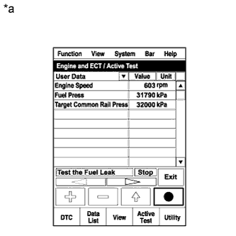
Start the engine.*1
Enter the following menus: Powertrain / Engine / Active Test / Test the Fuel Leak.*2
Text in Illustration *a Reference
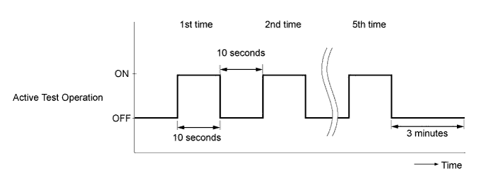
(Active Test Operation)
 |
Perform the following test 5 times with on/off intervals of 10 seconds: Active Test / Test the Fuel Leak.*3
Allow the engine to idle for 3 minutes or more after performing the Active Test for the fifth time.
- HINT:
- When the Active Test "Test the Fuel Leak" is used to change the pump control mode, the actual fuel pressure inside the common rail drops below the target fuel pressure when the Active Test is off, but this is normal and does not indicate a pump malfunction.
Enter the following menus: Powertrain / Engine / DTC.
Read Current DTCs.
Clear the DTCs (HILUX_TGN26 RM000000PDK0X3X.html).
- HINT:
- It is necessary to clear the DTCs, as DTC P1604 or P1605 may be stored when air is bled from the fuel system after replacing or repairing fuel system parts.
Repeat steps *1 to *3.
Enter the following menus: Powertrain / Engine / DTC.
Read Current DTCs.
- OK:
- No DTCs are output.
| 6. INSPECT FOR COOLANT LEAK |
- CAUTION:
- Do not remove the radiator reservoir cap while the engine and radiator are still hot. Pressurized, hot engine coolant and steam may be released and cause serious burns.
- NOTICE:
- Before each inspection, turn the A/C switch off.
Fill the radiator with coolant and attach a radiator cap tester.
Warm up the engine.
Using the radiator cap tester, increase the pressure inside the radiator to 118 kPa (1.2 kgf/cm2, 17 psi), and check that the pressure does not drop.
If the pressure drops, check the hoses, radiator and water pump for leaks. If no external leaks are found, check the heater core, cylinder block and head.
| 7. INSPECT FOR FUEL LEAK |
Perform the Active Test.
Connect the intelligent tester to the DLC3.
Turn the ignition switch to ON.
Turn the intelligent tester on.
Enter the following menus: Powertrain / Engine / Active Test.
Perform the Active Test.
Intelligent Tester Display Test Part Control Range Diagnostic Note Test the Fuel Leak Pressurize common rail interior and check for fuel leaks Stop/Start - The fuel pressure inside the common rail increases to the specified value and the engine speed increases to 2000 rpm when the Active Test is performed.
- The above conditions are maintained while the Active Test is being performed.
- The fuel pressure inside the common rail increases to the specified value and the engine speed increases to 2000 rpm when the Active Test is performed.