Dtc C1282/82 Center Differential Lock Position Switch Malfunction (Test Mode Dtc)
Brake. Hilux. Tgn26, 36 Kun25, 26, 35, 36 Ggn25
DESCRIPTION
WIRING DIAGRAM
INSPECTION PROCEDURE
CHECK TERMINAL VOLTAGE (EXI TERMINAL)
CHECK TEST MODE DTC
CHECK HARNESS AND CONNECTOR (EXI CIRCUIT)
DTC C1282/82 Center Differential Lock Position Switch Malfunction (Test Mode DTC) |
DESCRIPTION
DTC C1282/82 is output only in Test Mode.DTC Code
| DTC Detection Condition
| Trouble area
|
C1282/82
| Detected only during Test Mode.
| - Transfer system
- Harness or connector
- Skid control ECU (Brake actuator assembly)
|
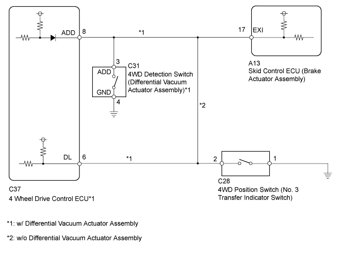
WIRING DIAGRAM
INSPECTION PROCEDURE
- NOTICE:
- Before disconnecting the connector, make sure that there are no problems with the connection.
- After disconnecting the connector, make sure that the connector case and terminals are not deformed or corroded.
| 1.CHECK TERMINAL VOLTAGE (EXI TERMINAL) |
Set the vehicle to the 4WD state using the transfer shift lever.
Disconnect the skid control ECU (brake actuator assembly) connector.
Measure the voltage according to the value(s) in the table below.
- Standard Voltage:
Tester Connection
| Condition
| Specified Condition
|
A13-17 (EXI) - Body ground
| - Ignition switch ON
- Transfer shift position H4
| Below 1.5 V
|
Connect the skid control ECU (brake actuator assembly) connector.
Set the vehicle to the 2WD state using the transfer shift lever.
Disconnect the skid control ECU (brake actuator assembly) connector.
Measure the voltage according to the value(s) in the table below.
- Standard Voltage:
Tester Connection
| Condition
| Specified Condition
|
A13-17 (EXI) - Body ground
| - Ignition switch ON
- Transfer shift position H2
| 11 to 14 V
|
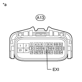
Text in Illustration*a
| Front view of wire harness connector
(to Skid Control ECU [Brake Actuator Assembly])
|
Switch the vehicle to Test Mode, perform the H2 to L4 shift operation check, and then check that DTC C1282/82 is not stored (HILUX_TGN26 RM000000XHT090X.html).
ResultResult
| Proceed to
|
DTC is stored
| A
|
DTC is not stored
| B
|
| 3.CHECK HARNESS AND CONNECTOR (EXI CIRCUIT) |
Turn the ignition switch off.
Disconnect the skid control ECU (brake actuator assembly) connector.
w/ Differential Vacuum Actuator Assembly:
Disconnect the 4WD detection switch (differential vacuum actuator assembly) connector.
w/o Differential Vacuum Actuator Assembly:
Disconnect the 4WD position switch (No. 3 transfer indicator switch) connector.
w/ Differential Vacuum Actuator Assembly:
Disconnect the 4 wheel drive control ECU connector.
Measure the resistance according to the value(s) in the table below.
- Standard Resistance:
w/ Differential Vacuum Actuator Assembly:Tester Connection
| Condition
| Specified Condition
|
A13-17 (EXI) - C31-3 (ADD)
| Always
| Below 1 Ω
|
A13-17 (EXI) - C37-8 (ADD)
| Always
| Below 1 Ω
|
A13-17 (EXI) - Body ground
| Always
| 10 kΩ or higher
|
C31-4 (GND) - Body ground
| Always
| Below 1 Ω
|
w/o Differential Vacuum Actuator Assembly:Tester Connection
| Condition
| Specified Condition
|
A13-17 (EXI) - C28-2
| Always
| Below 1 Ω
|
A13-17 (EXI) - Body ground
| Always
| 10 kΩ or higher
|
C28-1 - Body ground
| Always
| Below 1 Ω
|
| | REPAIR OR REPLACE HARNESS OR CONNECTOR |
|
|