Valve Body Assembly Inspection
Drivetrain. Hilux. Tgn26, 36 Kun25, 26, 35, 36 Ggn25
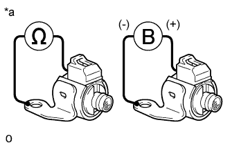
INSPECT SHIFT SOLENOID VALVE SR
INSPECT SHIFT SOLENOID VALVE SLU AND SLT
INSPECT SHIFT SOLENOID VALVE SL1 AND SL2
INSPECT SHIFT SOLENOID VALVE S1
INSPECT SHIFT SOLENOID VALVE S2
Valve Body Assembly -- Inspection |
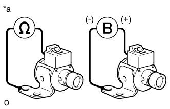
| 1. INSPECT SHIFT SOLENOID VALVE SR |
Measure the resistance according to the value(s) in the table below.
- Standard Resistance:
Tester Connection
| Condition
| Specified Condition
|
Shift solenoid valve SR connector terminal - Shift solenoid valve SR body
| 20°C (68°F)
| 11 to 15 Ω
|
Text in Illustration*a
| Component without harness connected
(Shift Solenoid Valve SR)
|
Apply 12 V of battery voltage to the shift solenoid valve and check that the valve moves and makes an operating noise.
- OK:
Measurement Condition
| Specified Condition
|
- Battery positive (+) → Shift solenoid valve SR connector
- Battery negative (-) → Shift solenoid valve SR body
| Valve moves and makes an operating noise
|
If the result is not as specified, replace the solenoid valve.
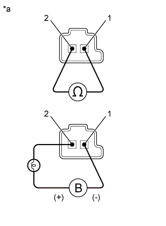
| 2. INSPECT SHIFT SOLENOID VALVE SLU AND SLT |
Measure the resistance according to the value(s) in the table below.
- Standard Resistance:
Tester Connection
| Condition
| Specified Condition
|
1 - 2
| 20°C (68°F)
| 5.0 to 5.6 Ω
|
Apply 12 V of battery voltage to the shift solenoid valve and check that the valve moves and makes an operating noise.
- OK:
Measurement Condition
| Specified Condition
|
- Battery positive (+) with a 21 W bulb → Terminal 2
- Battery negative (-) → Terminal 1
| Valve moves and makes an operating noise
|
Text in Illustration*a
| Component without harness connected
(Shift Solenoid Valve)
|
If the result is not as specified, replace the solenoid valve.
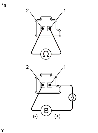
| 3. INSPECT SHIFT SOLENOID VALVE SL1 AND SL2 |
Measure the resistance according to the value(s) in the table below.
- Standard Resistance:
Tester Connection
| Condition
| Specified Condition
|
1 - 2
| 20°C (68°F)
| 5.0 to 5.6 Ω
|
Apply 12 V of battery voltage to the shift solenoid valve and check that the valve moves and makes an operating noise.
- OK:
Measurement Condition
| Specified Condition
|
- Battery positive (+) with a 21 W bulb → Terminal 1
- Battery negative (-) → Terminal 2
| Valve moves and makes an operating noise
|
Text in Illustration*a
| Component without harness connected
(Shift Solenoid Valve)
|
If the result is not as specified, replace the solenoid valve.
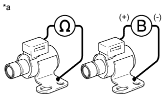
| 4. INSPECT SHIFT SOLENOID VALVE S1 |
Measure the resistance according to the value(s) in the table below.
- Standard Resistance:
Tester Connection
| Condition
| Specified Condition
|
Shift solenoid valve S1 connector terminal - Shift solenoid valve S1 body
| 20°C (68°F)
| 11 to 15 Ω
|
Apply 12 V of battery voltage to the shift solenoid valve and check that the valve moves and makes an operating noise.
- OK:
Measurement Condition
| Specified Condition
|
- Battery positive (+) → Shift solenoid valve S1 connector
- Battery negative (-) → Shift solenoid valve S1 body
| Valve moves and makes an operating noise
|
Text in Illustration*a
| Component without harness connected
(Shift Solenoid Valve S1)
|
If the result is not as specified, replace the solenoid valve.
| 5. INSPECT SHIFT SOLENOID VALVE S2 |
Measure the resistance according to the value(s) in the table below.
- Standard Resistance:
Tester Connection
| Condition
| Specified Condition
|
Shift solenoid valve S2 connector terminal - Shift solenoid valve S2 body
| 20°C (68°F)
| 11 to 15 Ω
|
Apply 12 V of battery voltage to the shift solenoid valve and check that the valve moves and makes an operating noise.
- OK:
Measurement Condition
| Specified Condition
|
- Battery positive (+) → Shift solenoid valve S2 connector
- Battery negative (-) → Shift solenoid valve S2 body
| Valve moves and makes an operating noise
|
Text in Illustration*a
| Component without harness connected
(Shift Solenoid Valve S2)
|
If the result is not as specified, replace the solenoid valve.