Unlock Warning Switch Removal
Door Lock. Hilux. Tgn26, 36 Kun25, 26, 35, 36 Ggn25
PRECAUTION
DISCONNECT CABLE FROM NEGATIVE BATTERY TERMINAL
REMOVE LOWER INSTRUMENT PANEL FINISH PANEL SUB-ASSEMBLY
REMOVE STEERING COLUMN LOWER COVER
REMOVE STEERING COLUMN UPPER COVER
REMOVE TRANSPONDER KEY AMPLIFIER (w/ Engine Immobiliser System)
REMOVE IGNITION SWITCH LOCK CYLINDER ASSEMBLY
REMOVE UNLOCK WARNING SWITCH ASSEMBLY
Unlock Warning Switch -- Removal |
- NOTICE:
- After turning the ignition switch off, waiting time may be required before disconnecting the cable from the battery terminal. Therefore, make sure to read the disconnecting the cable from the battery terminal notice before proceeding with work (HILUX_TGN26 RM000004QR1006X.html).
| 2. DISCONNECT CABLE FROM NEGATIVE BATTERY TERMINAL |
- NOTICE:
- When disconnecting the cable, some systems need to be initialized after the cable is reconnected (HILUX_TGN26 RM000004QR300CX.html).
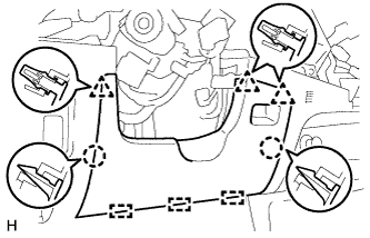
| 3. REMOVE LOWER INSTRUMENT PANEL FINISH PANEL SUB-ASSEMBLY |
Detach the 2 claws, 3 clips and 3 guides and remove the lower instrument panel finish panel.
| 4. REMOVE STEERING COLUMN LOWER COVER |
Remove the 3 bolts and lower cover.
| 5. REMOVE STEERING COLUMN UPPER COVER |
Detach the claw and remove the upper cover.
| 6. REMOVE TRANSPONDER KEY AMPLIFIER (w/ Engine Immobiliser System) |
Using a screwdriver, widen the claw attached to the upper bracket by approximately 1.0 mm (0.039 in.).
Pull out the transponder key amplifier with the claw open.
Disconnect the connector and transponder key amplifier.
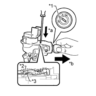
| 7. REMOVE IGNITION SWITCH LOCK CYLINDER ASSEMBLY |
Turn the ignition switch to ACC.
Insert the tip of a screwdriver into the hole in the steering column upper bracket, as shown in the illustration, and pull the ignition switch lock cylinder out until its claw comes into contact with the stopper of the steering column upper bracket.
Text in Illustration*1
| ACC
|
*2
| Claw
|
*3
| Stopper
|
*a
| Push
|
*b
| Pull
|
- NOTICE:
- Pull the ignition switch lock cylinder assembly out until its claw comes into contact with the stopper of the steering column bracket assembly upper. Otherwise, the following procedure cannot be conducted properly.
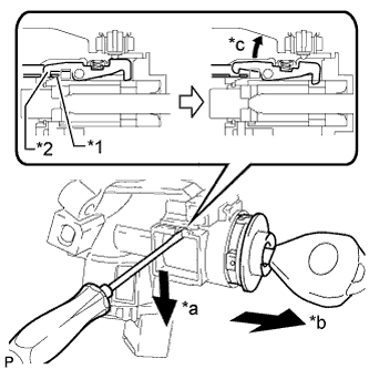
Insert the tip of a screwdriver into the hole in the steering column bracket and tilt it downward, as shown in the illustration, to detach the claw of the ignition switch lock cylinder. Then pull out the ignition switch lock cylinder.
Text in Illustration*1
| Stopper
|
*2
| Claw
|
*a
| Tilt
|
*b
| Pull out
|
*c
| Claw is detached
|
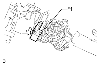
| 8. REMOVE UNLOCK WARNING SWITCH ASSEMBLY |
Disconnect the unlock warning switch connector.
Detach the 2 claws and slide the unlock warning switch as shown in the illustration.
Push in the pin, slide the unlock warning switch as shown in the illustration and remove it.
Text in Illustration*1
| Pin
|