DESCRIPTION
WIRING DIAGRAM
INSPECTION PROCEDURE
READ VALUE USING INTELLIGENT TESTER (STARTER SIGNAL)
CHECK STARTER (ST) RELAY (POWER SOURCE)
INSPECT STARTER (ST) RELAY
CHECK HARNESS AND CONNECTOR (STARTER (ST) RELAY - BODY GROUND)
CHECK HARNESS AND CONNECTOR (STARTER (ST) RELAY - IGNITION SWITCH)
INSPECT IGNITION SWITCH ASSEMBLY
CHECK HARNESS AND CONNECTOR (STARTER (ST) RELAY - PARK/NEUTRAL POSITION SWITCH)
INSPECT PARK/NEUTRAL POSITION SWITCH ASSEMBLY
CHECK HARNESS AND CONNECTOR (PARK/NEUTRAL POSITION SWITCH - IGNITION SWITCH)
INSPECT IGNITION SWITCH ASSEMBLY
SFI SYSTEM (w/o Secondary Air Injection System) - Starter Signal Circuit |
DESCRIPTION
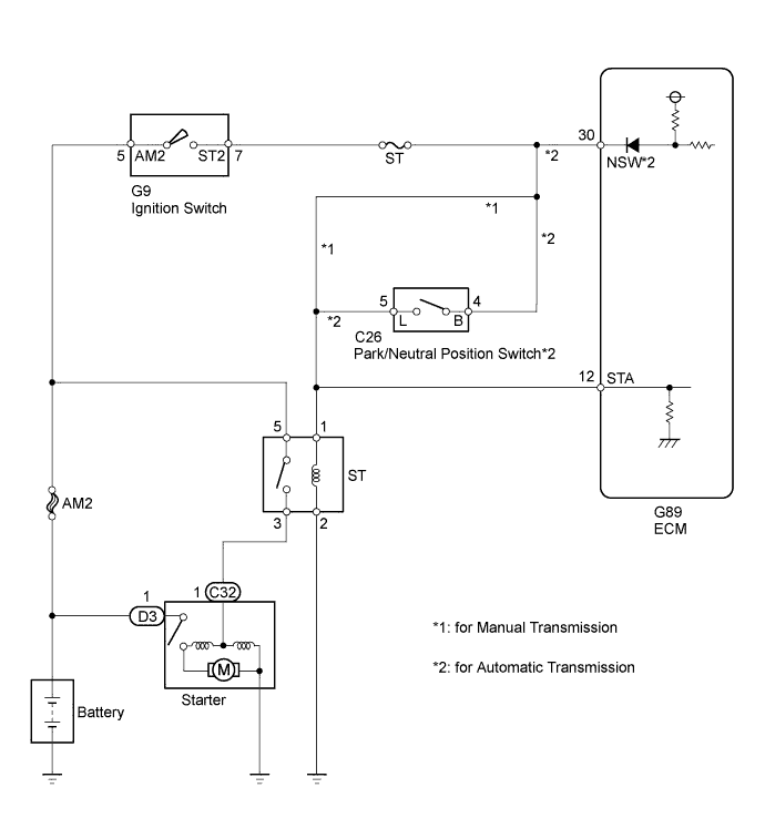
While the engine is being cranked, current flows from terminal ST2 of the ignition switch through the park/neutral position switch (for A/T) or directly (for M/T) to terminal STA of the ECM (STA signal).
WIRING DIAGRAM
INSPECTION PROCEDURE
- NOTICE:
- Inspect the fuses for circuits related to this system before performing the following inspection procedure.
- HINT:
- This inspection procedure is based on the premise that the engine can crank normally. If the engine cannot crank normally, proceed to the problem symptoms table (HILUX_TGN26 RM000000PDG0O9X.html).
| 1.READ VALUE USING INTELLIGENT TESTER (STARTER SIGNAL) |
Connect the intelligent tester to the DLC3.
Turn the ignition switch to ON.
Turn the intelligent tester on.
Enter the following menus: Powertrain / Engine and ECT / Data List / Starter Signal.
Read the value.
- OK:
Ignition Switch Position
| Starter Signal
|
ON
| Close (Starter signal OFF)
|
START
| Open (Starter signal ON)
|
| 2.CHECK STARTER (ST) RELAY (POWER SOURCE) |
Remove the starter (ST) relay from the engine room relay block and junction block.
Measure the voltage according to the value(s) in the table below.
- Standard Voltage:
Tester Connection
| Condition
| Specified Condition
|
Starter (ST) relay terminal 2 - Body ground
| Engine cranking
| 11 to 14 V
|
- HINT:
- The engine does not crank because the relay is not installed.
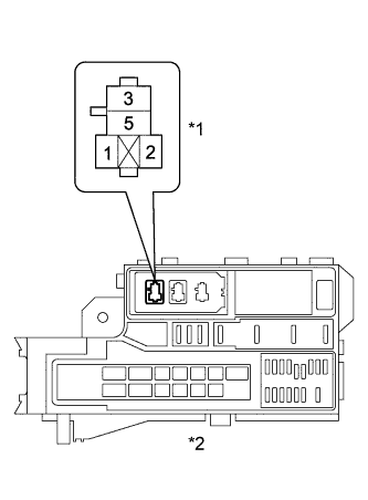
Text in Illustration*1
| Starter (ST) Relay
|
*2
| Engine Room Relay Block and Junction Block Assembly
|
ResultResult
| Proceed to
|
OK
| A
|
NG (for Manual Transaxle)
| B
|
NG (for Automatic Transaxle)
| C
|
| 3.INSPECT STARTER (ST) RELAY |
Inspect the starter (ST) relay (HILUX_TGN26 RM000000WPQ05MX_01_0001.html).
| | REPLACE STARTER (ST) RELAY |
|
|
| 4.CHECK HARNESS AND CONNECTOR (STARTER (ST) RELAY - BODY GROUND) |
Remove the starter (ST) relay from the engine room relay block and junction block.
Measure the resistance according to the value(s) in the table below.
- Standard Resistance:
Tester Connection
| Condition
| Specified Condition
|
Starter (ST) relay terminal 2 - Body ground
| Always
| Below 1 Ω
|
ResultResult
| Proceed to
|
OK (for Manual Transaxle)
| A
|
OK (for Automatic Transaxle)
| B
|
NG
| C
|
| | REPAIR OR REPLACE HARNESS OR CONNECTOR (ECM - PARK/NEUTRAL POSITION SWITCH) |
|
|
| | REPAIR OR REPLACE HARNESS OR CONNECTOR (STARTER (ST) RELAY - BODY GROUND) |
|
|
| A |
|
|
|
| REPAIR OR REPLACE HARNESS OR CONNECTOR (ECM - IGNITION SWITCH) |
|
| 5.CHECK HARNESS AND CONNECTOR (STARTER (ST) RELAY - IGNITION SWITCH) |
Remove the starter (ST) relay from the engine room relay block and junction block.
Disconnect the ignition switch connector.
Measure the resistance according to the value(s) in the table below.
- Standard Resistance:
Tester Connection
| Condition
| Specified Condition
|
Starter (ST) relay terminal 1 - G9-7 (ST2)
| Always
| Below 1 Ω
|
Starter (ST) relay terminal 1 or G9-7 (ST2) - Body ground
| Always
| 10 kΩ or higher
|
| | REPAIR OR REPLACE HARNESS OR CONNECTOR (STARTER (ST) RELAY - IGNITION SWITCH) |
|
|
| 6.INSPECT IGNITION SWITCH ASSEMBLY |
Inspect the ignition switch assembly (HILUX_TGN26 RM00000135X01BX.html).
| OK |
|
|
|
| REPAIR OR REPLACE HARNESS OR CONNECTOR (IGNITION SWITCH - BATTERY) |
|
| 7.CHECK HARNESS AND CONNECTOR (STARTER (ST) RELAY - PARK/NEUTRAL POSITION SWITCH) |
Remove the starter (ST) relay from the engine room relay block and junction block.
Disconnect the park/neutral position switch connector.
Measure the resistance according to the value(s) in the table below.
- Standard Resistance:
Tester Connection
| Condition
| Specified Condition
|
ST relay terminal 1 - C26-5 (L)
| Always
| Below 1 Ω
|
ST relay terminal 1 or C26-5 (L) - Body ground
| Always
| 10 kΩ or higher
|
| | REPAIR OR REPLACE HARNESS OR CONNECTOR (STARTER (ST) RELAY - PARK/NEUTRAL POSITION SWITCH) |
|
|
| 8.INSPECT PARK/NEUTRAL POSITION SWITCH ASSEMBLY |
Inspect the park/neutral position switch assembly (HILUX_TGN26 RM0000010NA02NX.html).
| 9.CHECK HARNESS AND CONNECTOR (PARK/NEUTRAL POSITION SWITCH - IGNITION SWITCH) |
Disconnect the park/neutral position switch connector.
Disconnect the ignition switch connector.
Measure the resistance according to the value(s) in the table below.
- Standard Resistance:
Tester Connection
| Condition
| Specified Condition
|
C26-4 (B) - G9-7 (ST2)
| Always
| Below 1 Ω
|
C26-4 (B) or G9-7 (ST2) - Body ground
| Always
| 10 kΩ or higher
|
| | REPAIR OR REPLACE HARNESS OR CONNECTOR (PARK/NEUTRAL POSITION SWITCH - IGNITION SWITCH) |
|
|
| 10.INSPECT IGNITION SWITCH ASSEMBLY |
Inspect the ignition switch assembly (HILUX_TGN26 RM00000135X01BX.html).
| OK |
|
|
|
| REPAIR OR REPLACE HARNESS OR CONNECTOR (IGNITION SWITCH - BATTERY) |
|