Intake System (W/ Dpf) System Diagram
INTAKE AIR CONTROL SYSTEM ILLUSTRATION
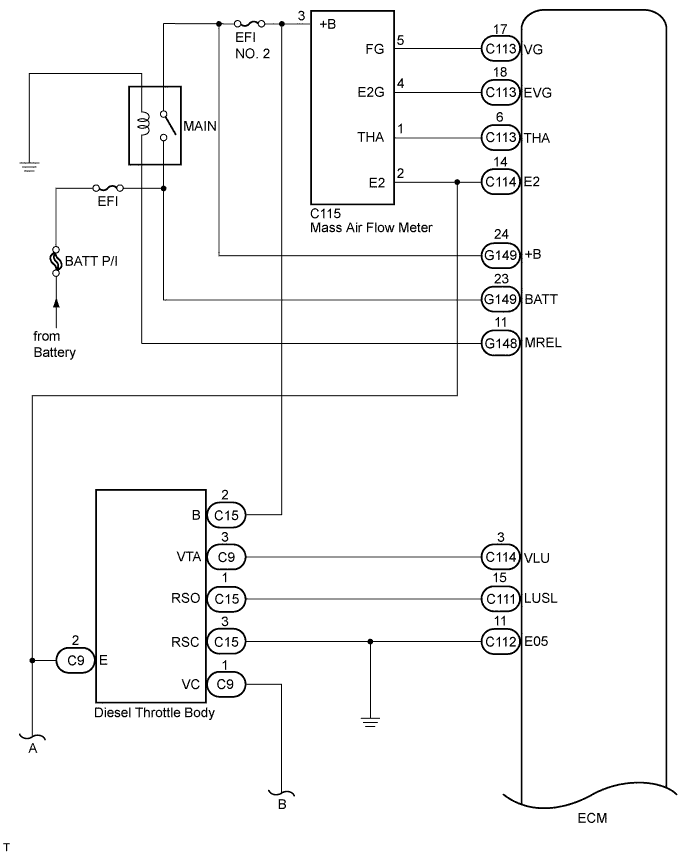
INTAKE AIR CONTROL SYSTEM WIRING DIAGRAM
TURBOCHARGER SYSTEM ILLUSTRATION
TURBOCHARGER SYSTEM WIRING DIAGRAM
Intake System (W/ Dpf) -- System Diagram |
| INTAKE AIR CONTROL SYSTEM ILLUSTRATION |
- The manifold absolute pressure sensor detects the manifold pressure by using a built-in sensor unit. The ECM determines the basic injection duration and injection advance timing based on the output voltage by the manifold absolute pressure sensor.
- The manifold absolute pressure sensor monitors the absolute pressure inside the intake manifold (default is 0 kPa (0 mmHg, 0 in.Hg)), so that the ECM controls the air-fuel ratio at the proper level under any driving conditions, without the influence of fluctuations in the atmospheric pressure due to factors such as high altitude, etc.
Text in Illustration*1
| ECM
| *2
| Air Cleaner
|
*3
| Mass Air Flow Meter
| *4
| Intercooler
|
*5
| Intake Air Temperature Sensor
| *6
| Diesel Throttle Body
|
*7
| Manifold Absolute Pressure Sensor
| *8
| Engine Coolant Temperature Sensor
|
*9
| Turbocharger
| *10
| Turbocharger Actuator
- Turbocharger Variable Nozzle Motor
- Turbocharger Variable Nozzle Sensor
|
*11
| Crankshaft Position Sensor
| -
| -
|
| INTAKE AIR CONTROL SYSTEM WIRING DIAGRAM |
| TURBOCHARGER SYSTEM ILLUSTRATION |
- The turbocharger system is comprised of the Variable Nozzle (VN) type turbocharger and ECM.
- The turbocharger has a nozzle vane which opens and closes to control the volume of the exhaust gas flowing into the turbine. This, in turn, controls the boost pressure. When the nozzle vane moves towards the closing direction, the pressure increases. When the vane moves towards the opening direction, the pressure decreases.
- The turbocharger actuator built onto the compressor housing side activates the nozzle vane. The nozzle vane position sensor built onto the actuator detects the opening angle of the nozzle vane. The ECM receives a nozzle vane position sensor signal. Based on this signal, the ECM operates the DC motor and controls the turbocharger opening angle.
- The ECM performs control to obtain the nozzle vane position for the optimal pressure in accordance with the driving conditions.

Text in Illustration*1
| ECM
| *2
| Air Cleaner
|
*3
| Mass Air Flow Meter
| *4
| Intercooler
|
*5
| Intake Air Temperature Sensor
| *6
| Diesel Throttle Body
|
*7
| Manifold Absolute Pressure Sensor
| *8
| Engine Coolant Temperature Sensor
|
*9
| Turbocharger
| *10
| Turbocharger Actuator
- Turbocharger Variable Nozzle Motor
- Turbocharger Variable Nozzle Sensor
|
*11
| Crankshaft Position Sensor
| -
| -
|
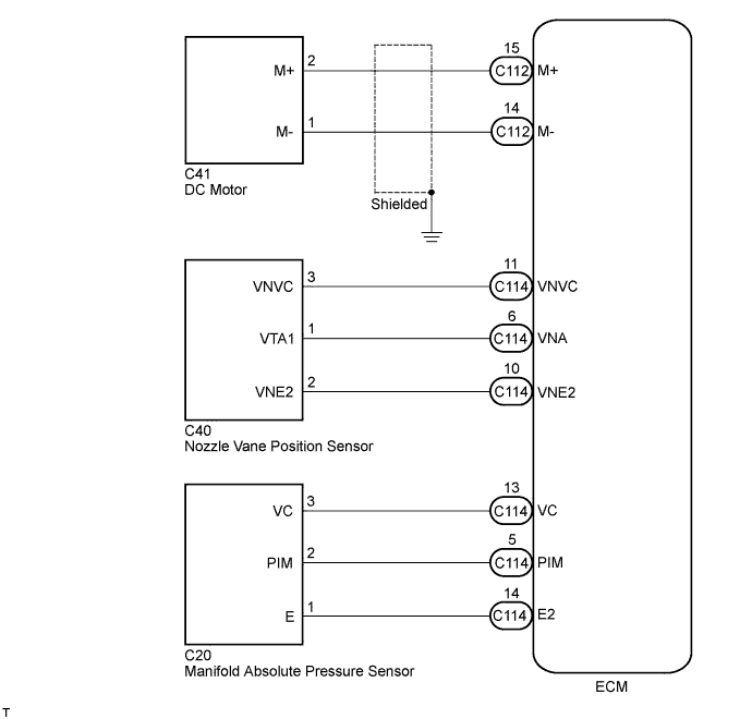
| TURBOCHARGER SYSTEM WIRING DIAGRAM |